AI Copilot Helps You Read the Source Code of DeepSeek 3FS
The speed of AI development is beyond imagination. For example, the VS Code Copilot Agent [1] can quickly read a large amount of code, understand the main components and interactions, and even draw class diagrams and flowcharts. It is truly a powerful tool for researching open-source projects. This article uses it to read the source code of DeepSeek 3FS [2] to generate explanations, riding the wave of current trends. The following text is all generated by AI, including the diagrams.
This article was also published to my WeiChat blog:
1. Introduction
DeepSeek 3FS is a high-performance, AI-native distributed file system designed to meet the demanding I/O patterns of large-scale model training and inference. Unlike traditional storage systems, it reimagines the storage stack in an AI-first manner—optimizing tensor data, parallel GPU access, and RDMA accelerated transfers. By tightly integrating metadata efficiency, hierarchical caching, and workload-aware data placement, DeepSeek 3FS transforms storage from a bottleneck into a performance driver, fundamentally changing the way data flows in modern AI infrastructure.
Delving into complex codebases like DeepSeek 3FS can feel like wandering in a dense forest without a map. However, with the right tools, what once seemed like insurmountable obstacles become a path of insight and discovery. In this article, we will explore the DeepSeek 3FS file system in detail, tracing its architecture and core mechanisms from the source code. In this process, we will heavily rely on a game-changing assistant: the VS Code Copilot Agent. With its ability to generate accurate and intuitive diagrams directly from code snippets, the Copilot Agent not only helps you read the code—it helps you understand the code. From call graphs to data flows to module relationships, it visualizes complexity in seconds, making it an indispensable tool for anyone trying to master large systems like DeepSeek 3FS.
2. 3FS Client Architecture (src/client)
This document provides an architectural overview of the client components in the 3FS system, including their structure, relationships, and main workflows.
2.1. Main Components and Functionalities
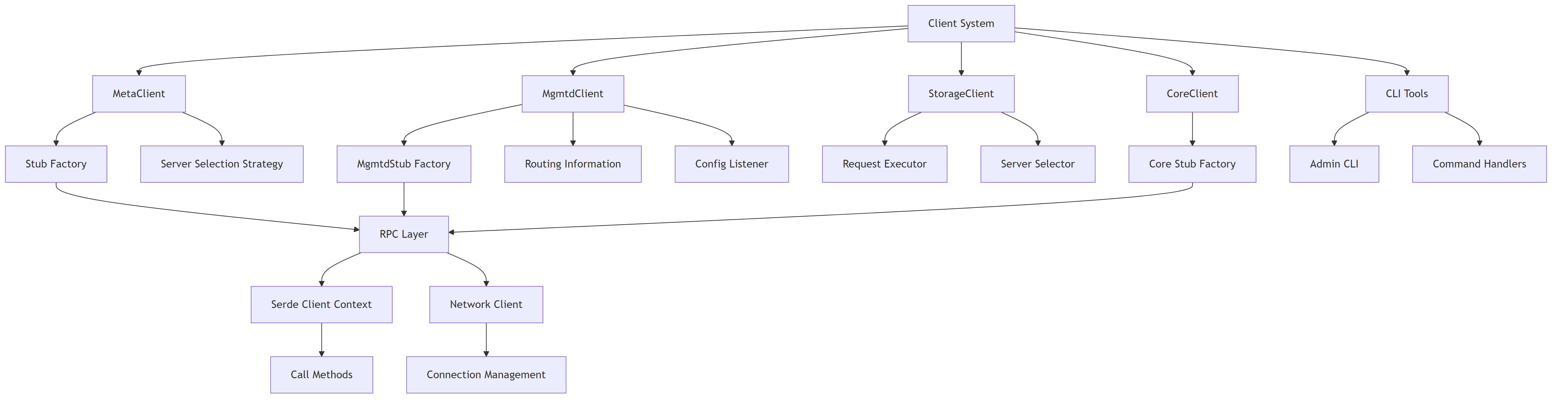
- MetaClient: Manages file metadata operations (create, open, close, stat, lookup, etc.) and communicates with metadata servers.
- MgmtdClient: Handles cluster management operations, maintains routing information, and manages client sessions.
- StorageClient: Responsible for data I/O operations (read/write chunks) and communicates with storage servers.
- CoreClient: Provides core functionality and system-level operations across the cluster.
- CLI Tools: Command-line utilities for administration and management of the 3FS system.
- Serde Layer: Serialization/deserialization framework for RPC communication.
- Network Layer: Manages connections and network communication with various servers.
2.2. Component Overview
The following diagram shows the high-level architecture and relationships between the main components in the client system.
2.3. Client Component Structure
2.3.1. MetaClient Architecture
This diagram illustrates the internal structure of MetaClient and its relationships with other components.
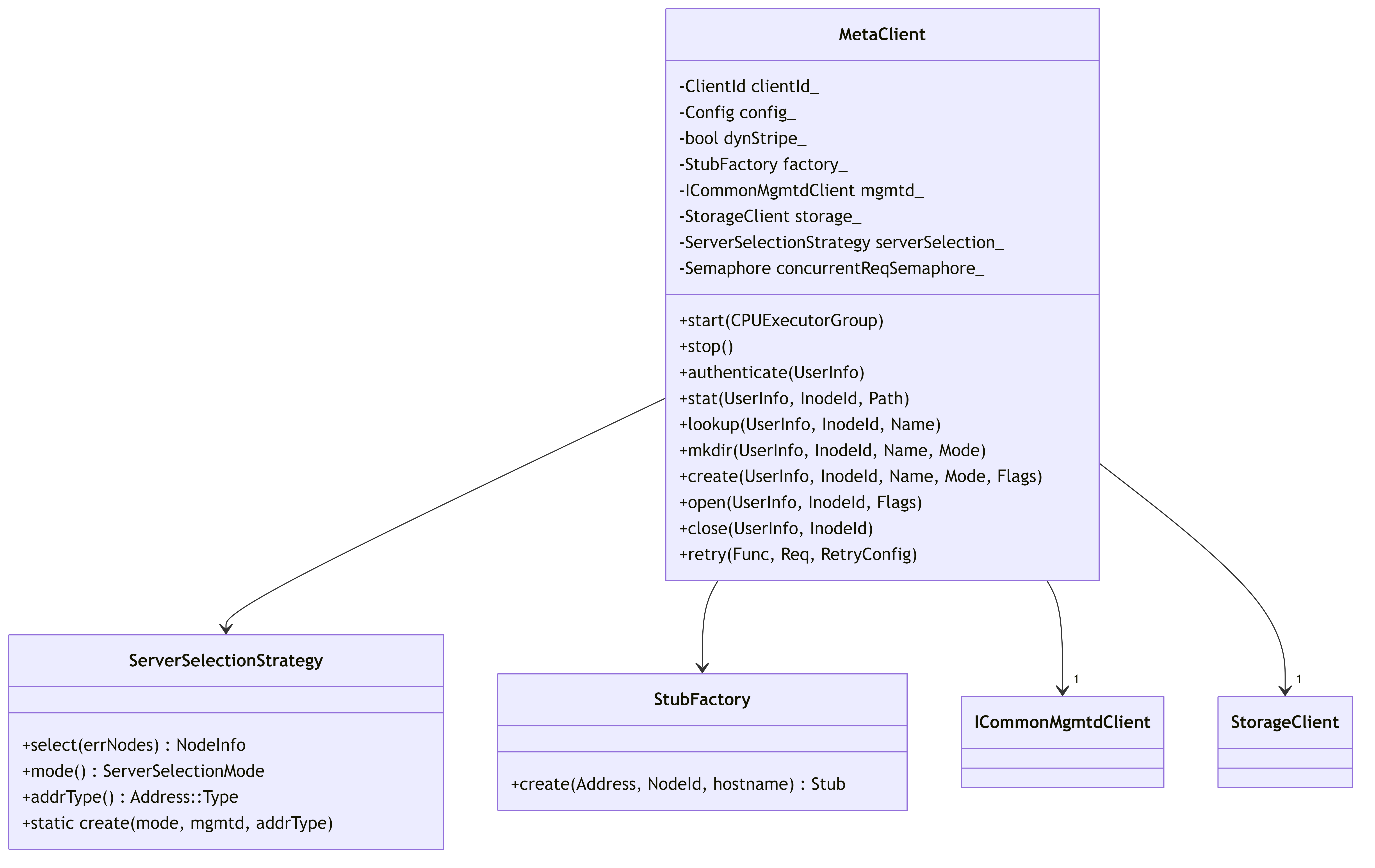
MetaClient Functionality:
- Provides file system metadata operations (stat, lookup, mkdir, create, open, close)
- Implements retry logic for handling server failures
- Uses server selection strategy to choose the appropriate metadata server
- Manages concurrent request limits through semaphore
- Handles background tasks like closing files and pruning sessions
2.3.2. MgmtdClient Architecture
This diagram shows the MgmtdClient structure and its key components for cluster management.
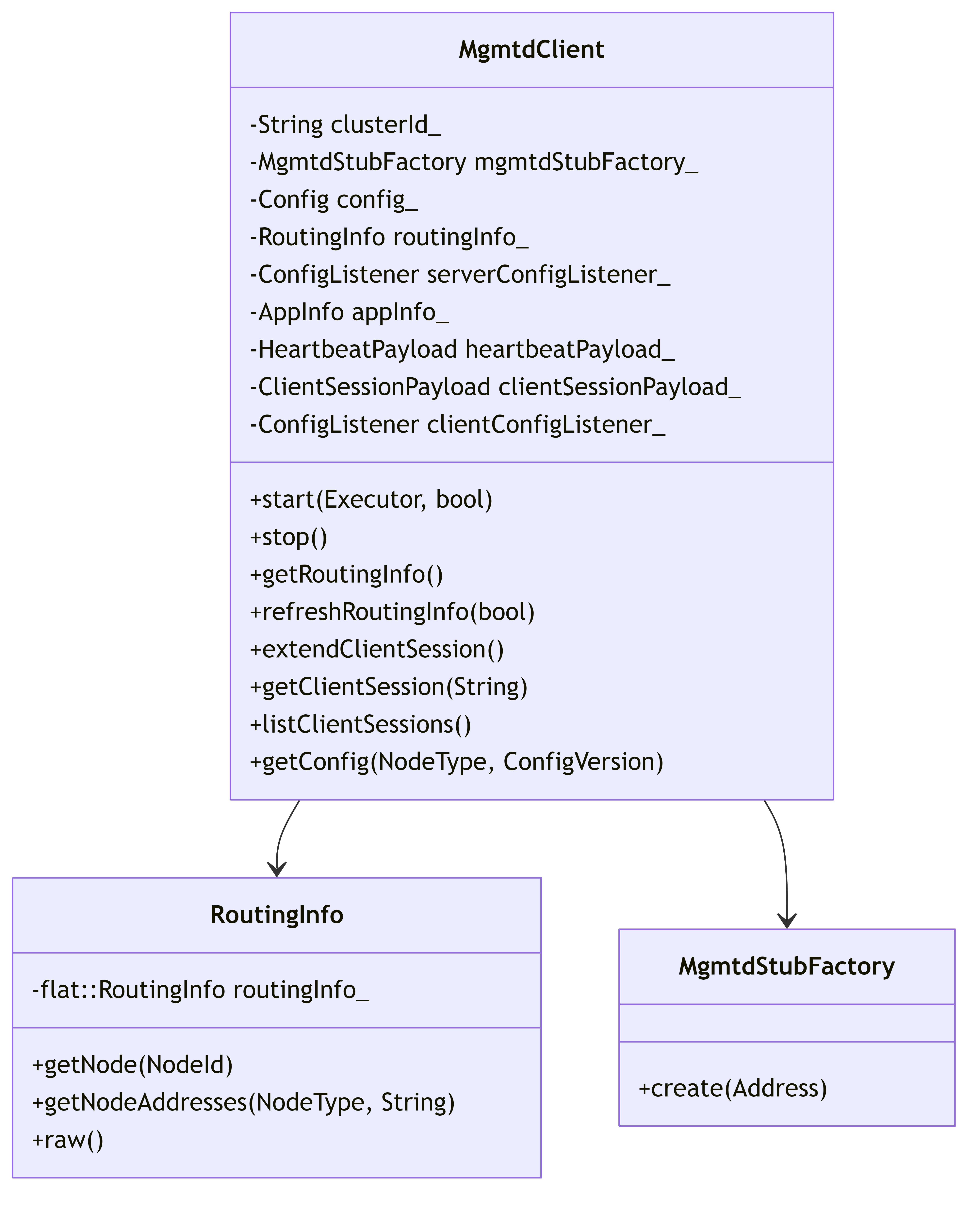
MgmtdClient Functionality:
- Maintains cluster routing information (which servers are available)
- Manages client sessions through creation and periodic extension
- Provides configuration management and updates
- Enables service discovery for other components
- Sends heartbeats to maintain connectivity with management servers
- Facilitates client identification and registration in the cluster
2.3.3. StorageClient Architecture
This diagram depicts the StorageClient structure and its components for handling data operations.
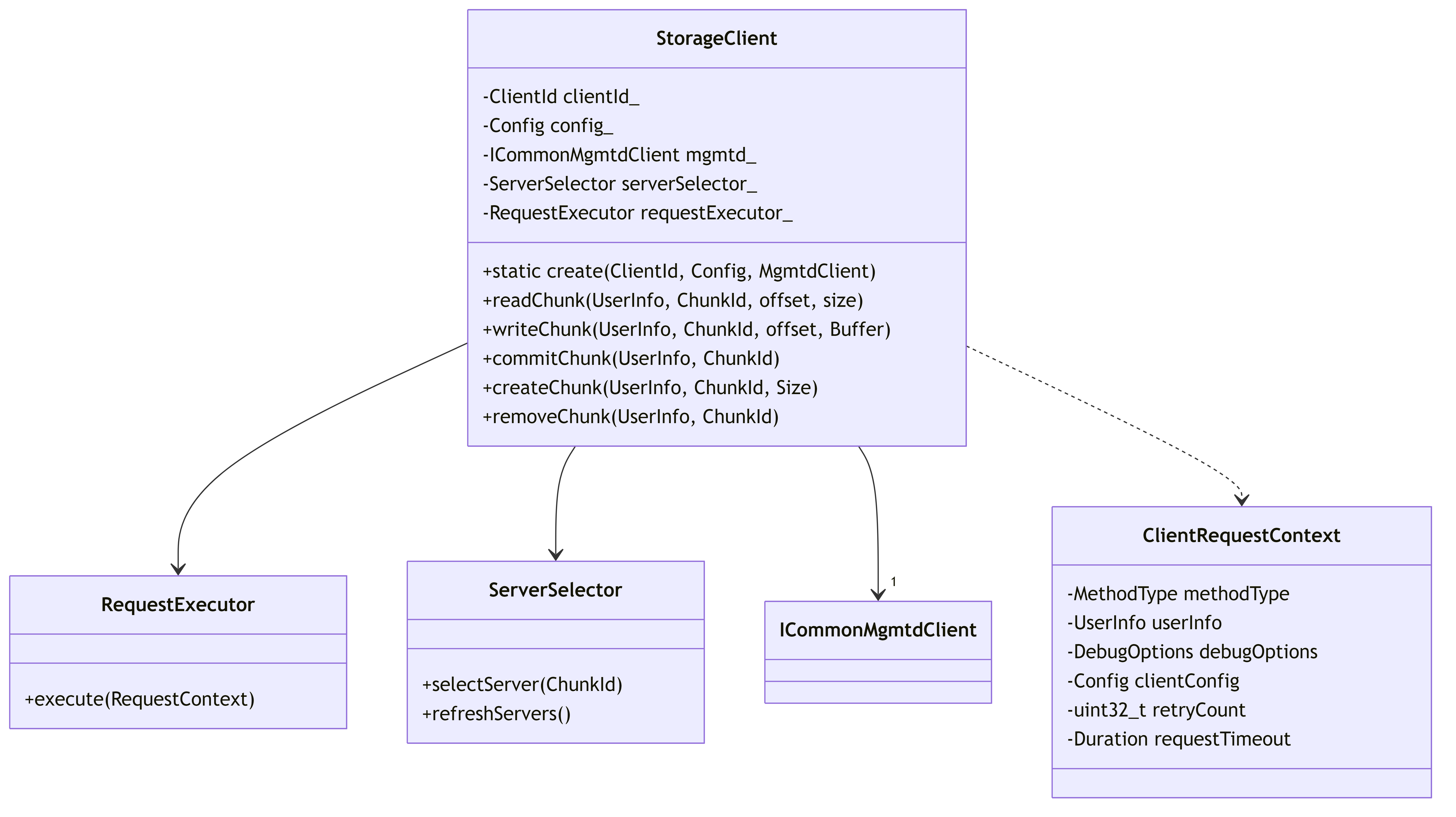
StorageClient Functionality:
- Handles data I/O operations (read/write chunks)
- Creates, commits, and removes storage chunks
- Selects appropriate storage servers for operations
- Implements retries and error handling for storage operations
- Maintains metrics and monitoring for storage operations
- Optimizes data transfer through configurable request handling
2.4. Network Communication
This diagram illustrates the sequence of events during RPC communication between client and server.
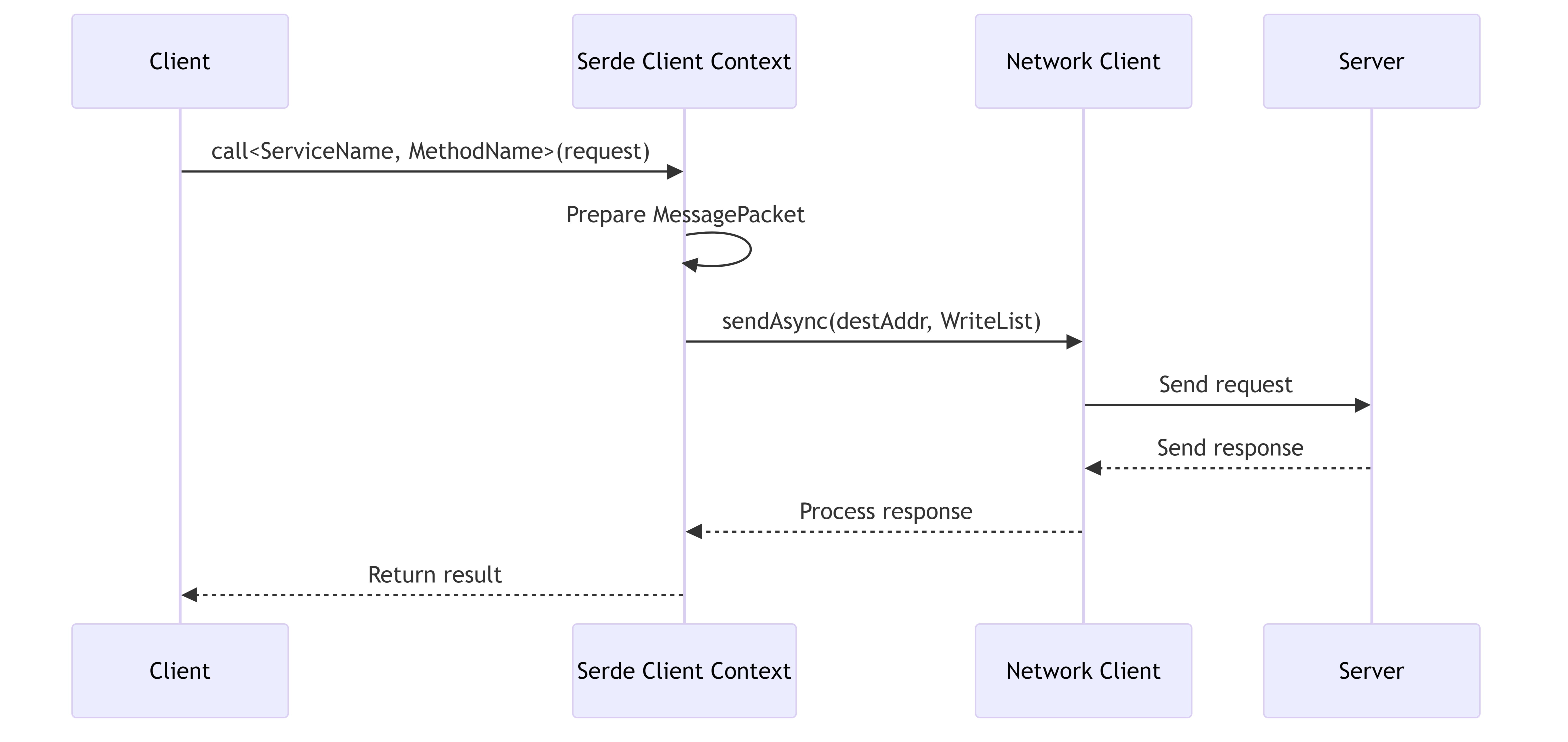
Network Communication Features:
- Serializes requests using the Serde framework
- Supports both synchronous and asynchronous RPC calls
- Manages network connections and reconnection strategies
- Handles timeouts and retries for failed requests
- Reports metrics on network latency and throughput
- Supports various transport protocols (TCP, RDMA)
2.5. Server Selection Workflow
This diagram shows how clients select servers for metadata operations, including error handling and retries.
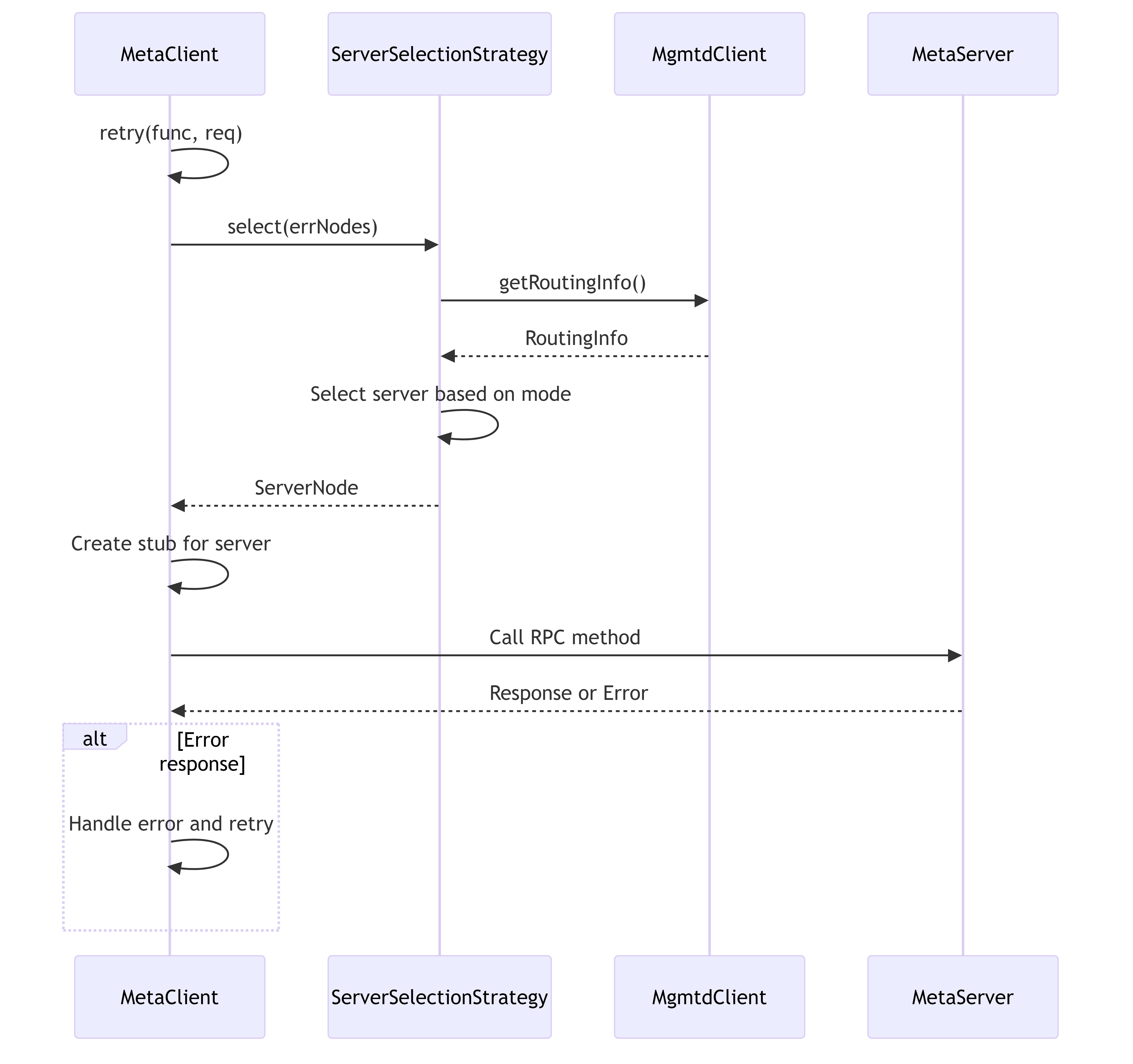
Server Selection Features:
- Multiple selection strategies (Random, Follow, RandomFollow)
- Tracks failed servers to avoid selecting them again
- Retrieves fresh routing information when needed
- Supports different network protocols for each server
- Implements configurable retry policies with exponential backoff
2.6. Remote Call Workflow
This diagram details the process of making remote calls from client to server, showing the internal components involved.
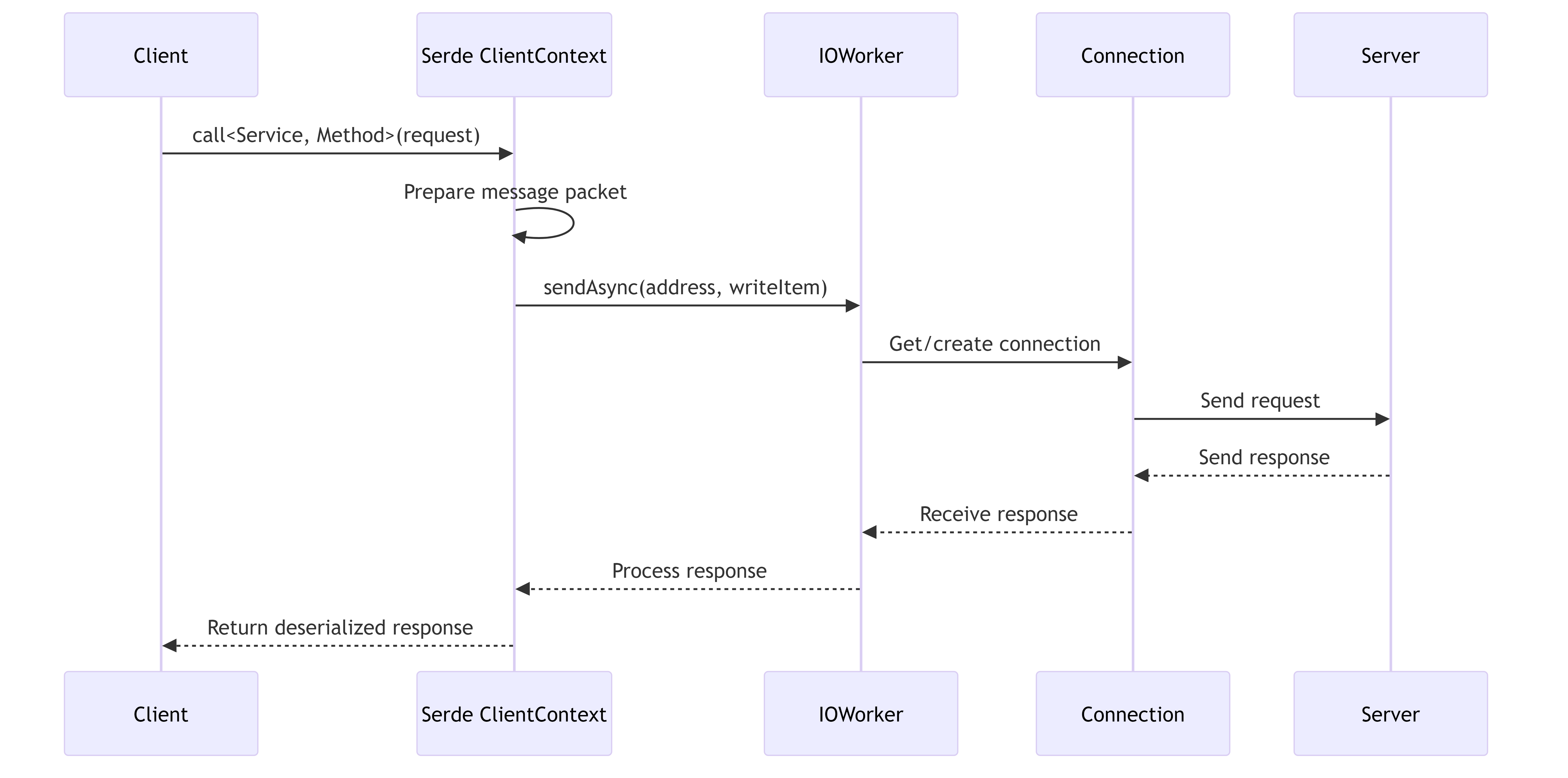
Remote Call Features:
- Supports both asynchronous (coroutine-based) and synchronous calls
- Handles connection pooling and reuse
- Implements request timeouts and cancellation
- Collects performance metrics (latency, throughput)
- Supports compression for large payloads
- Provides detailed error information for debugging
2.7. CLI Command Structure
This diagram shows the structure of the admin CLI tool and its command handlers.
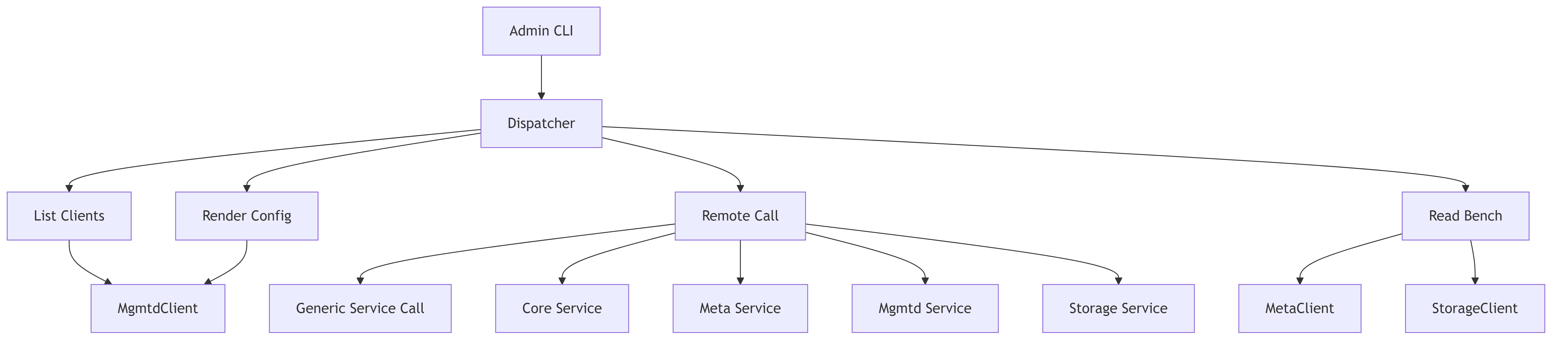
CLI Functionality:
- Provides administrative interface for the 3FS system
- Implements commands for debugging and monitoring
- Allows direct interaction with system services
- Supports rendering of configuration information
- Enables benchmarking and performance testing
- Facilitates client session management
2.8. Client Session Management
This diagram illustrates the lifecycle of a client session, from establishment to periodic extension.
Session Management Features:
- Establishes client identity in the cluster
- Maintains persistent sessions through heartbeats
- Implements retry logic for session establishment
- Handles session recovery after network failures
- Supports configuration updates during session lifetime
- Enables server-side tracking and management of clients
3. FoundationDB Integration Architecture in 3FS (src/fdb)
This document provides an overview of the FoundationDB (FDB) integration architecture in the 3FS system. It covers the main components, their structure, relationships, and workflows.
3.1. Overview
The FoundationDB integration in 3FS provides a robust key-value store implementation that interfaces with the FoundationDB database. The integration is designed around several core components that handle initialization, transactions, and database operations.
3.2. Component Architecture
3.2.1. Core Components
The following diagram shows the main components of the FDB integration and their relationships:
The diagram above shows the core components of the FoundationDB integration in 3FS:
FDBConfig: Configuration for FoundationDB connectionsFDBContext: Manages the lifecycle of the FoundationDB connectionDB: Represents a connection to a FoundationDB databaseTransaction: Wraps a native FoundationDB transactionFDBTransaction: Implements the 3FS transaction interface on top of FoundationDBFDBKVEngine: Provides a key-value engine implementation using FoundationDBHybridKvEngine: Allows using multiple key-value engines, including FoundationDB
3.2.2. Result Classes Hierarchy
The following diagram shows the result classes used to handle asynchronous operations with FoundationDB:
The Result template class hierarchy allows type-safe handling of different FoundationDB operation results.
3.3. Operational Workflows
3.3.1. Initialization Workflow
This diagram illustrates the initialization process of the FoundationDB integration, showing how the FDB network is set up and the DB instance is created.
3.3.2. Transaction Workflow
This diagram shows the workflow of a transaction, including how operations like get, set, and commit are handled through the various layers of the architecture.
3.3.3. Error Handling and Retry Workflow
This diagram illustrates how errors are handled and the retry mechanism for transient errors in FoundationDB transactions.
3.4. Operation Monitoring
The FDB integration includes monitoring capabilities through operation recorders:
The monitoring system uses specialized recorders for different types of operations, tracking metrics like:
- Total operation counts
- Failed operation counts
- Operation latencies
3.5. Key Components Functionality
3.5.1. FDBContext
The FDBContext class manages the lifecycle of the FoundationDB connection, including:
- Selecting the API version
- Configuring network options
- Setting up and running the network thread
- Creating database instances
3.5.2. DB
The DB class represents a connection to a FoundationDB database and provides:
- Static methods for global FoundationDB operations
- Database-level operations and options
- Creation of transaction objects
3.5.3. Transaction
The Transaction class wraps a native FoundationDB transaction and provides:
- Both read and write operations
- Transaction options and management
- Asynchronous operations using folly::coro::Task
3.5.4. FDBTransaction
The FDBTransaction class implements the 3FS transaction interface and provides:
- Higher-level transaction operations
- Error handling and conversion
- Integration with the monitoring system
3.5.5. FDBKVEngine
The FDBKVEngine class provides a key-value engine implementation using FoundationDB:
- Creates transactions that implement the 3FS transaction interfaces
- Manages the DB connection
3.5.6. HybridKvEngine
The HybridKvEngine allows using multiple key-value engines:
- Can be created with FoundationDB backing
- Can be created with in-memory backing
- Routes operations to the appropriate underlying engine
4. 3FS FUSE Architecture (src/fuse)
This document provides an overview of the FUSE (Filesystem in USErspace) implementation in the 3FS system. It includes component diagrams, workflow illustrations, and descriptions of the main functionalities.
4.1. Overview
The 3FS FUSE module implements a FUSE interface that allows the 3FS filesystem to be mounted as a standard filesystem in the operating system. It translates filesystem operations (e.g., read, write, mkdir) into appropriate calls to the underlying storage and metadata services.
4.2. Main Components
This diagram shows the main components of the FUSE implementation and their relationships.
4.3. Component Details
4.3.1. FuseApplication
The main application class that initializes the FUSE filesystem and handles the application lifecycle.
4.3.2. FuseClients
Central management class that:
- Maintains connections to metadata and storage services
- Manages inode cache and state
- Handles I/O operations and background tasks
- Coordinates periodic synchronization
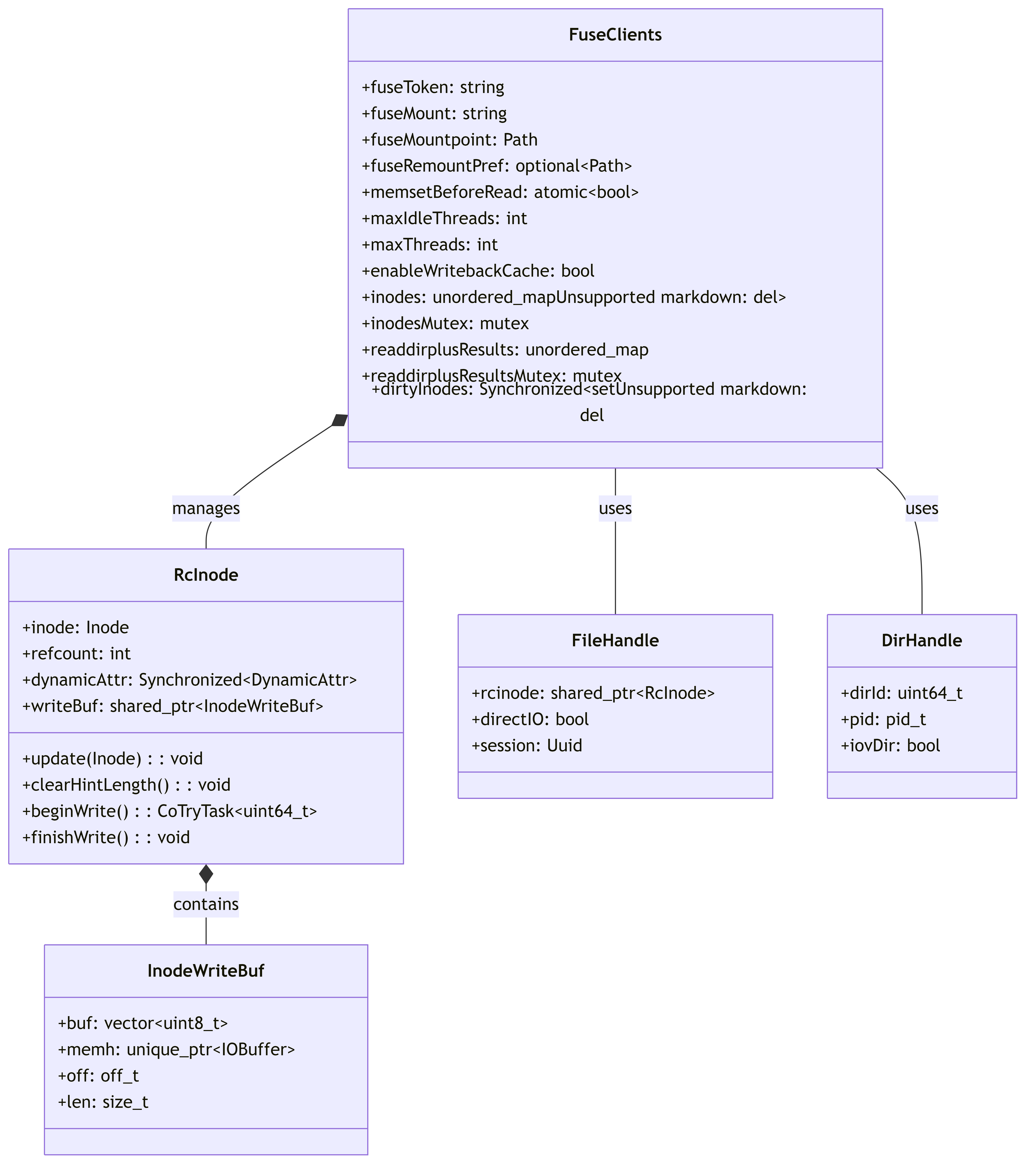
This diagram shows the internal structure of FuseClients and related classes.
4.3.3. FuseOperations (in FuseOps.cc)
Implements all FUSE filesystem operations required by the fuse_lowlevel_ops interface, including:
- File operations (read, write, create)
- Directory operations (mkdir, readdir)
- Attribute operations (getattr, setattr)
- Special operations (ioctl, xattr)
4.4. Main Workflows
4.4.1. File Read Workflow
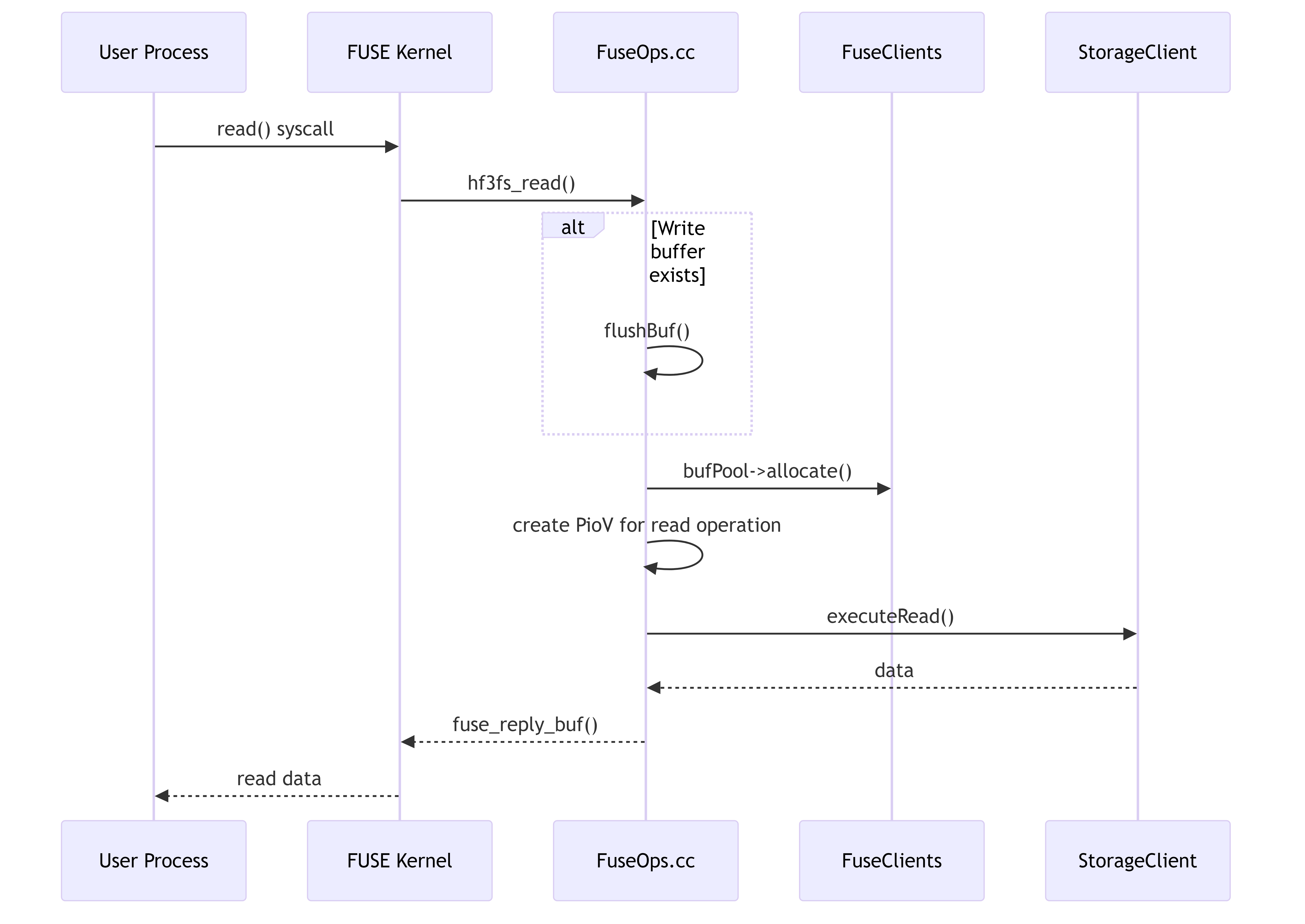
This diagram illustrates the flow of a read operation from a user process through the FUSE layer to the storage backend.
4.4.2. File Write Workflow
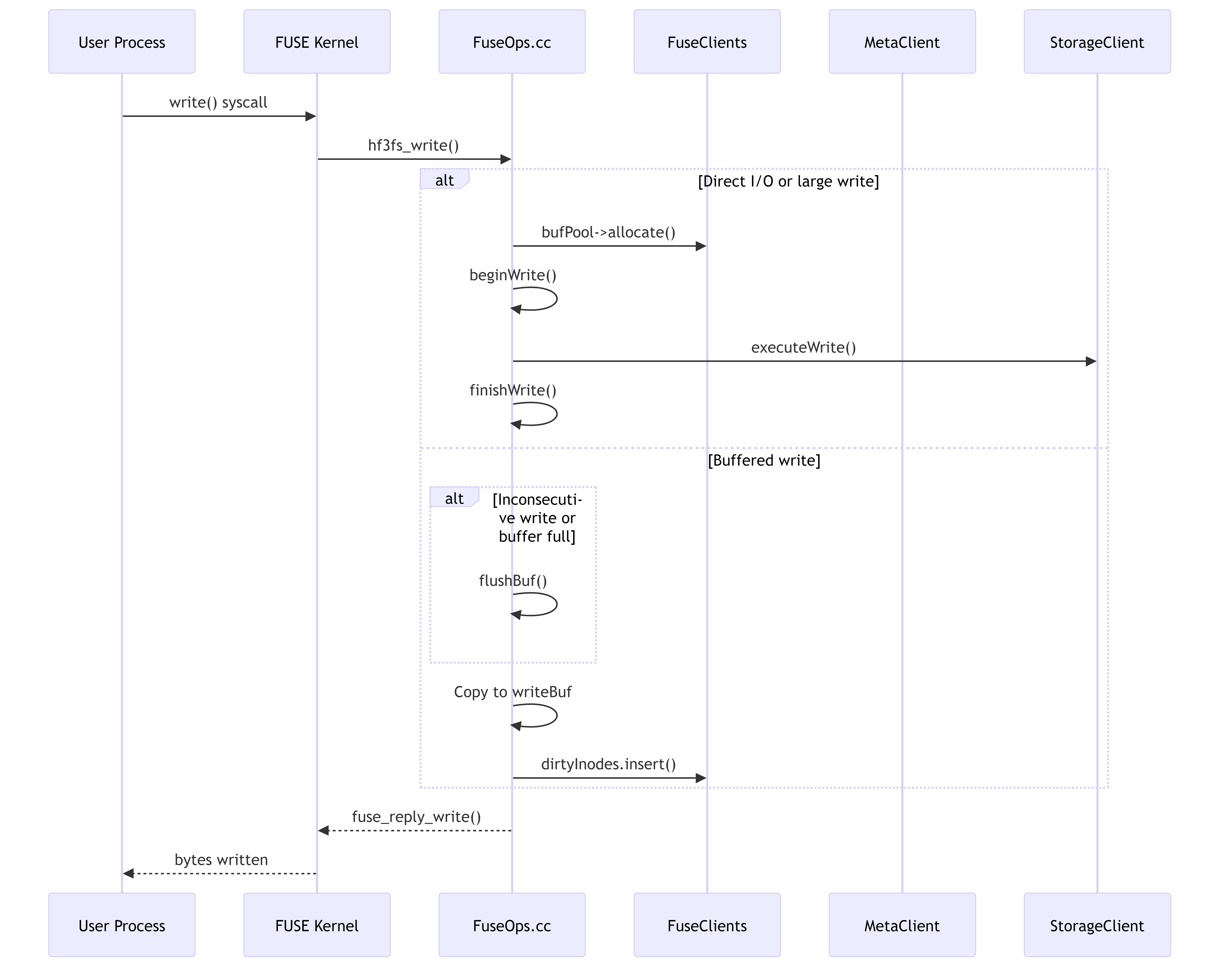
This diagram shows how write operations are processed, including both direct I/O and buffered write cases.
4.4.3. Periodic Sync Workflow
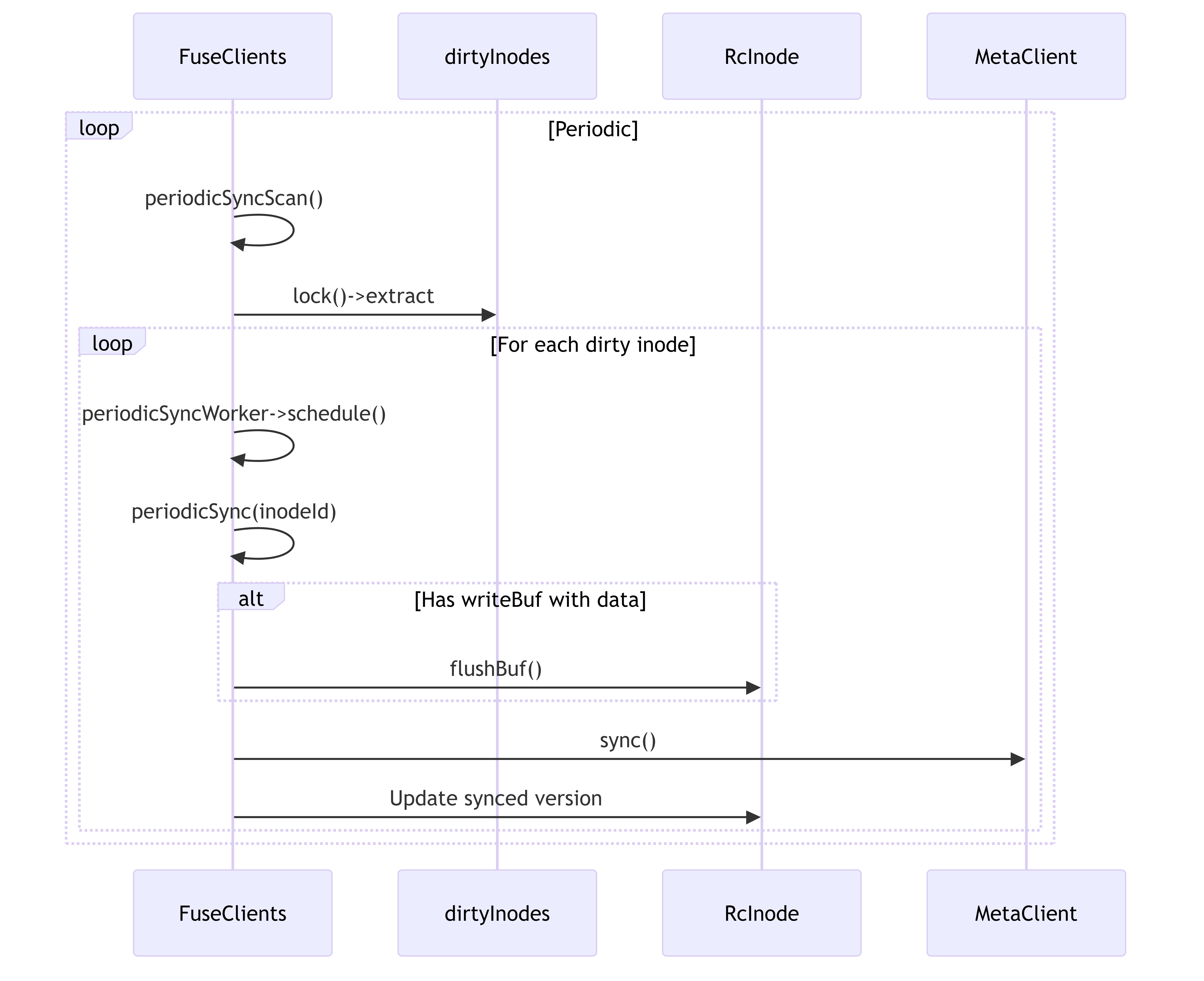
This diagram shows how dirty inodes are periodically synchronized with the metadata server.
4.5. IOCTL Operations
3FS implements custom IOCTL operations for special filesystem functionality:
These operations provide extended functionality for the filesystem that isn’t covered by standard POSIX operations.
4.6. I/O Ring and Buffer Management
This diagram shows how I/O operations are managed through ring buffers and memory pools.
4.7. Key Features and Optimizations
-
Write Buffering: Small writes are buffered to improve performance by reducing the number of operations to storage.
-
Periodic Sync: Background thread periodically syncs dirty inodes to ensure data durability.
-
Memory Management: Uses a buffer pool to efficiently manage memory for I/O operations.
-
Caching: Implements caching of inode metadata and directory entries to reduce calls to the metadata server.
-
Configurability: Provides extensive configuration options like read/write timeouts, buffer sizes, and sync intervals.
-
Optimized I/O: Uses PioV (Parallel I/O Vector) for efficient I/O operations to the storage backend.
-
Direct I/O Support: Supports direct I/O to bypass the kernel page cache when needed.
4.8. Conclusion
The 3FS FUSE implementation provides a complete POSIX filesystem interface on top of the distributed 3FS storage system. It balances performance and reliability through careful buffer management, caching, and synchronization strategies.
5. 3FS Metadata Service Architecture (src/meta)
This document provides an architectural overview of the metadata service implementation in the 3FS system. It includes component diagrams, internal structures, workflow illustrations, and descriptions of the main functionalities.
5.1. Overview
The metadata service is a critical component of the 3FS distributed filesystem, responsible for managing file system metadata including inodes, directories, file attributes, and namespace operations. It ensures consistency, durability, and high availability of metadata across the distributed system.
5.2. Main Components
This diagram shows the main components of the metadata service and their relationships.
5.3. Component Details
5.3.1. MetadataServer
The central server component that initializes and coordinates all metadata service functionality.
This diagram shows the internal structure of the MetadataServer and its configuration.
5.3.2. MetaStore
The core metadata storage system that manages inodes, directory entries, and namespace relationships.
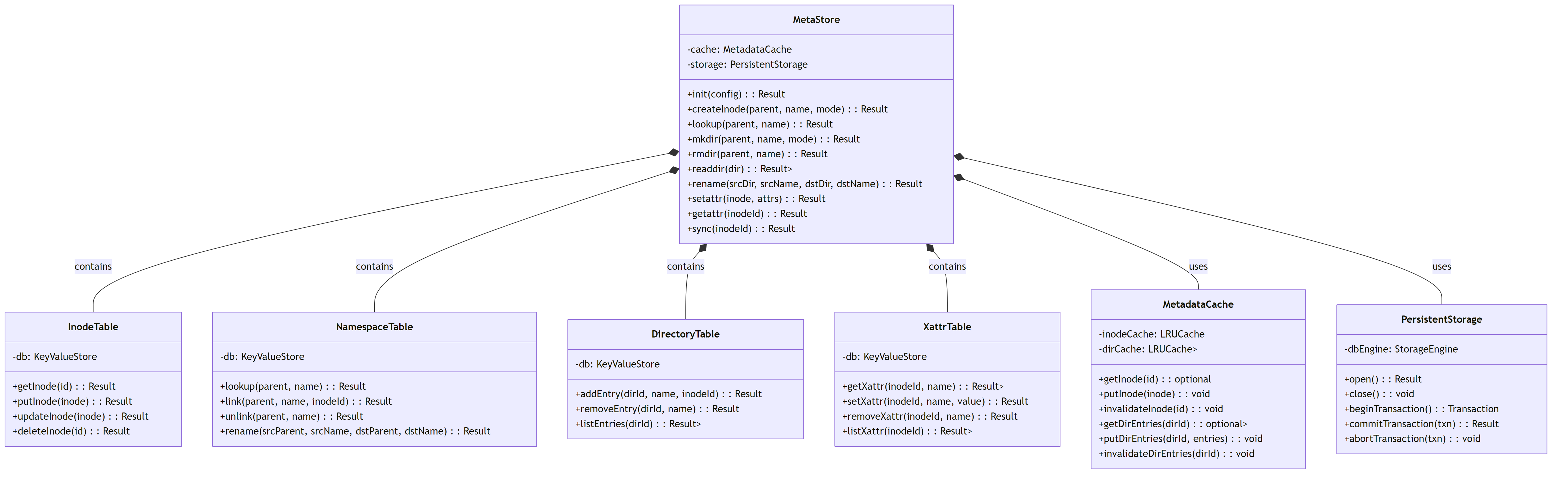
This diagram shows the detailed structure of the MetaStore and its sub-components.
5.3.3. RpcServer and MetaServiceImpl
The RPC interface that handles client requests and translates them into metadata operations.
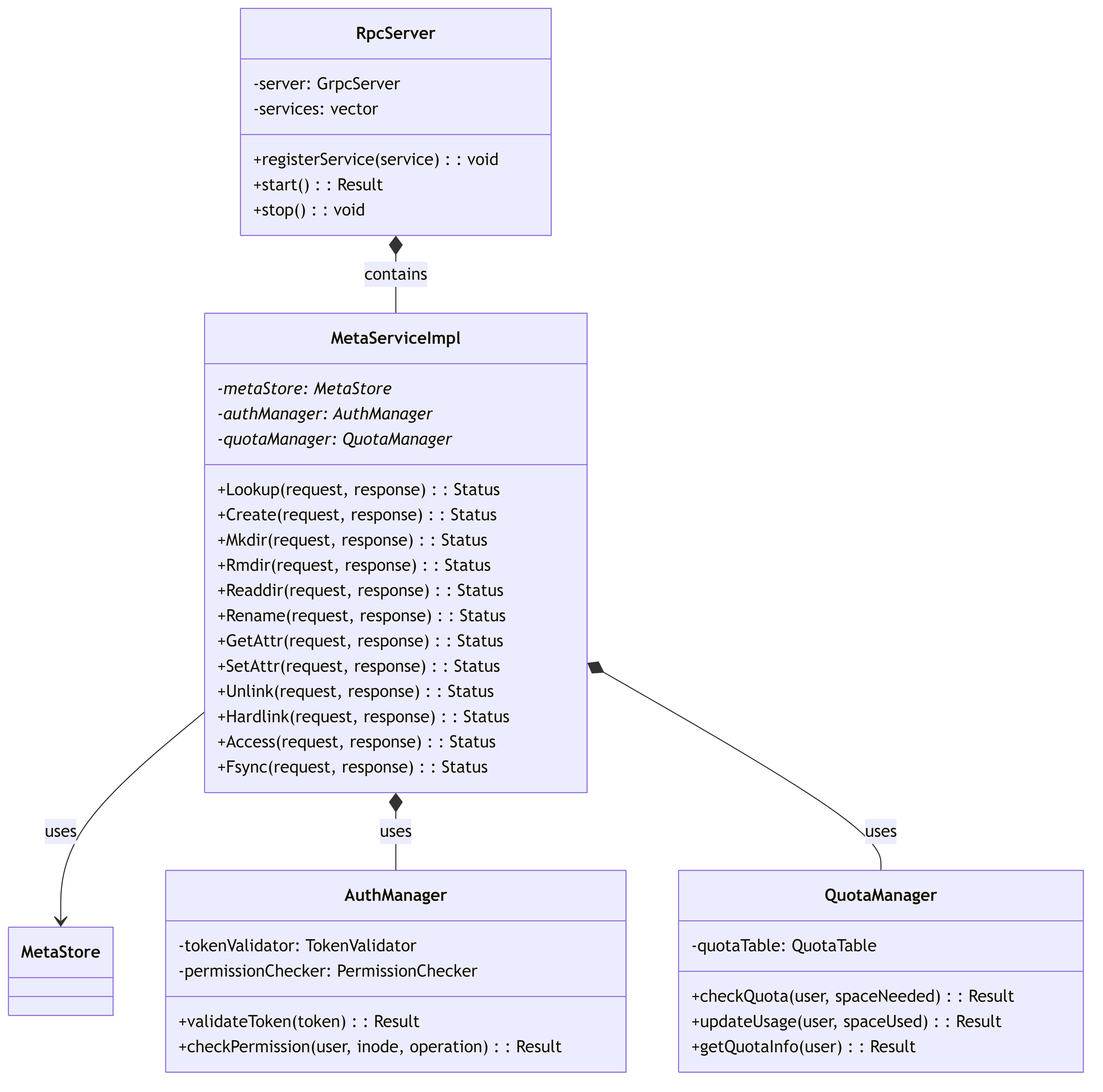
This diagram shows the RPC server components and their relationship with auth and quota management.
5.3.4. JournalManager
Manages write-ahead logging and recovery for metadata operations.
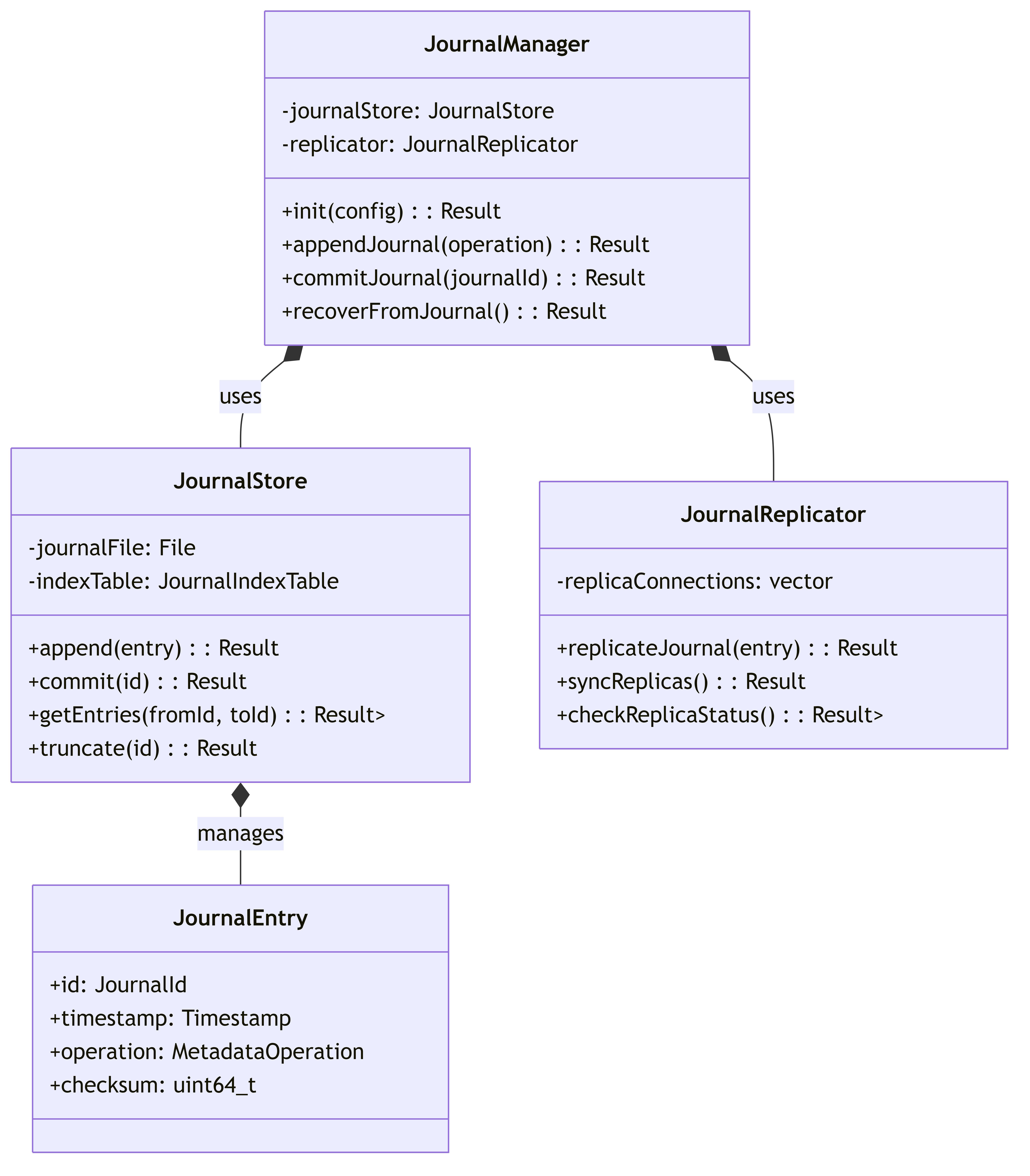
This diagram illustrates the journal management system for write-ahead logging.
5.4. Main Workflows
5.4.1. File Creation Workflow
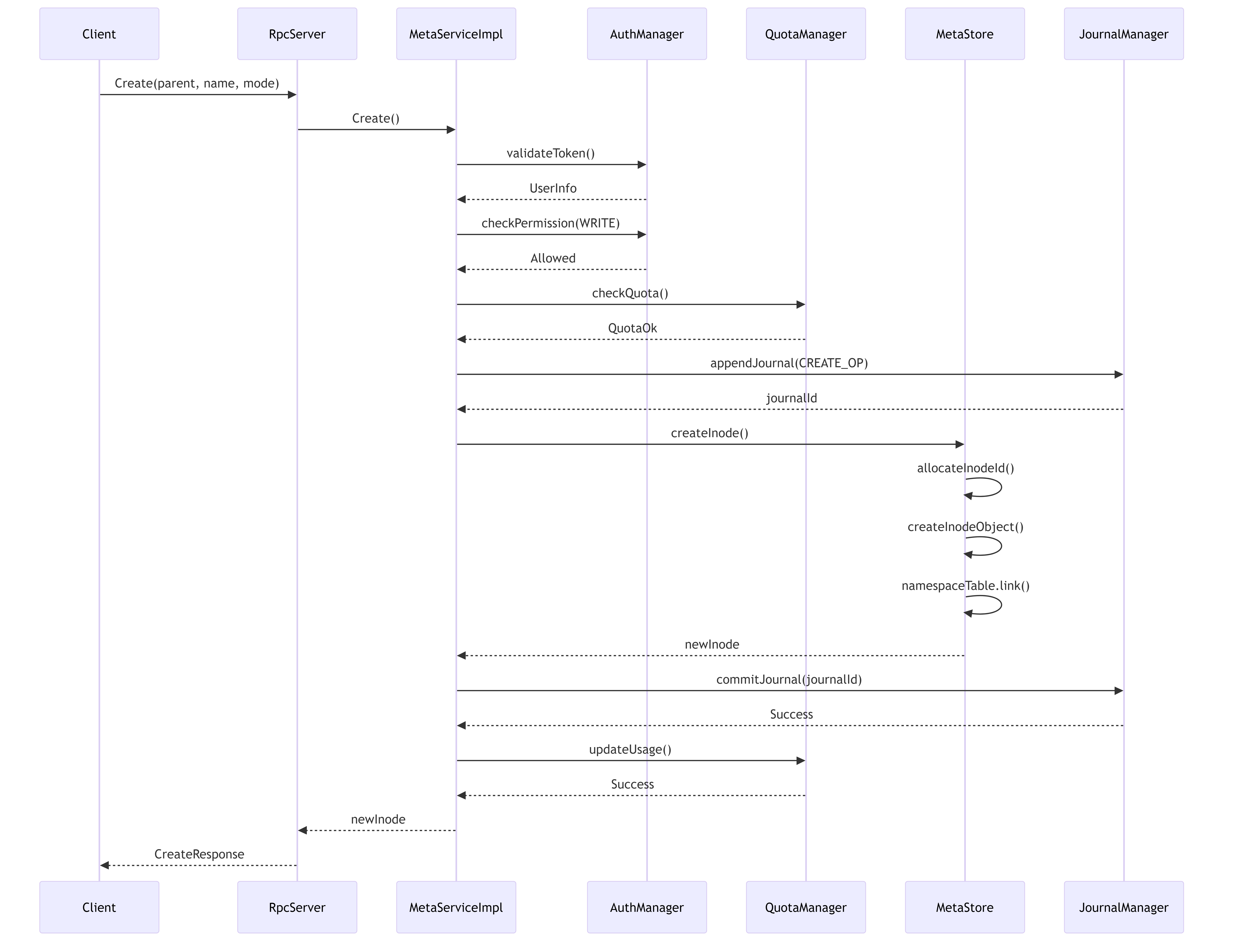
This diagram shows the workflow for creating a new file, including permission checks, journaling, and quota management.
5.4.2. Directory Listing Workflow
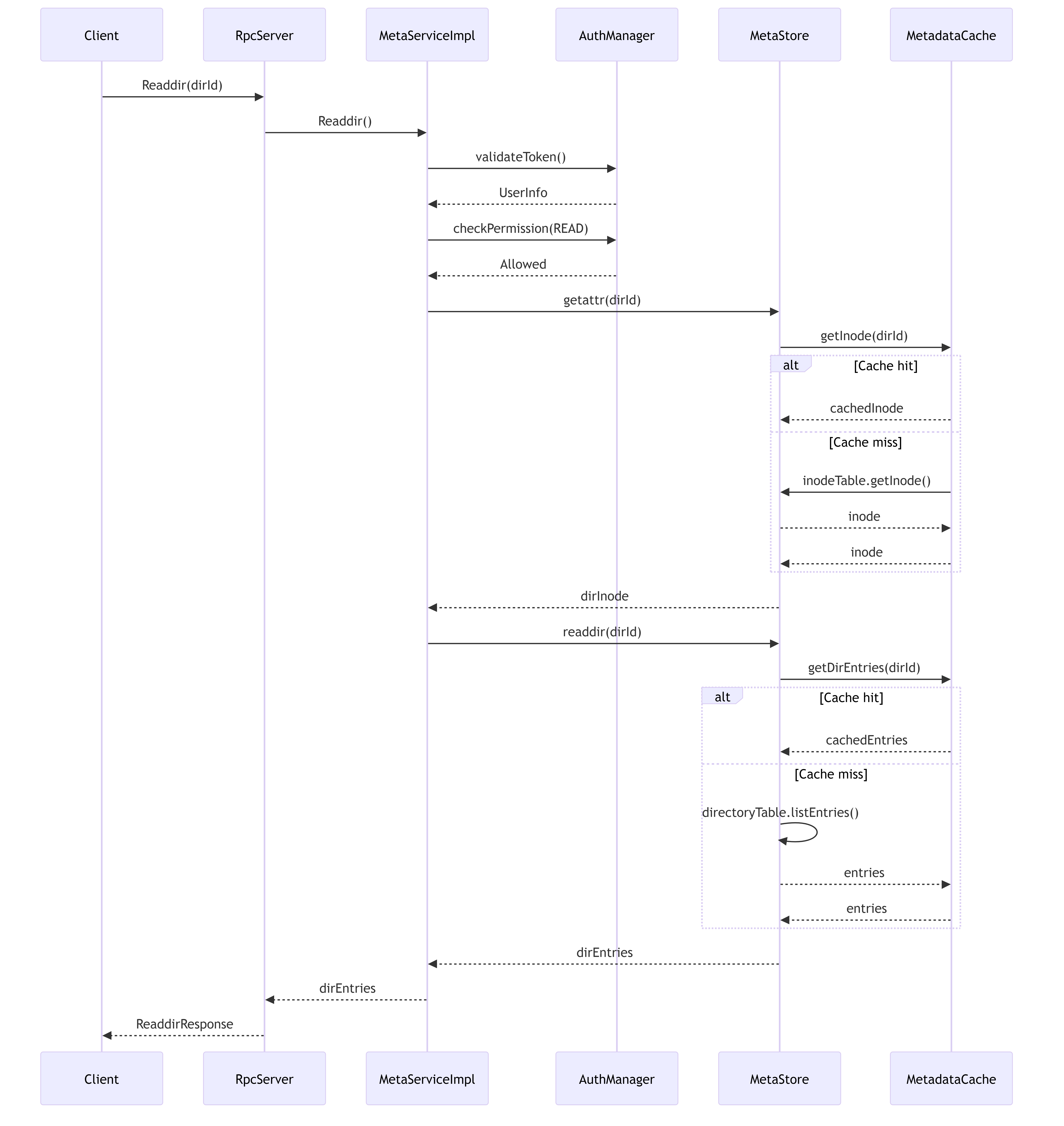
This diagram illustrates the directory listing workflow with cache interaction.
5.4.3. Rename Operation Workflow
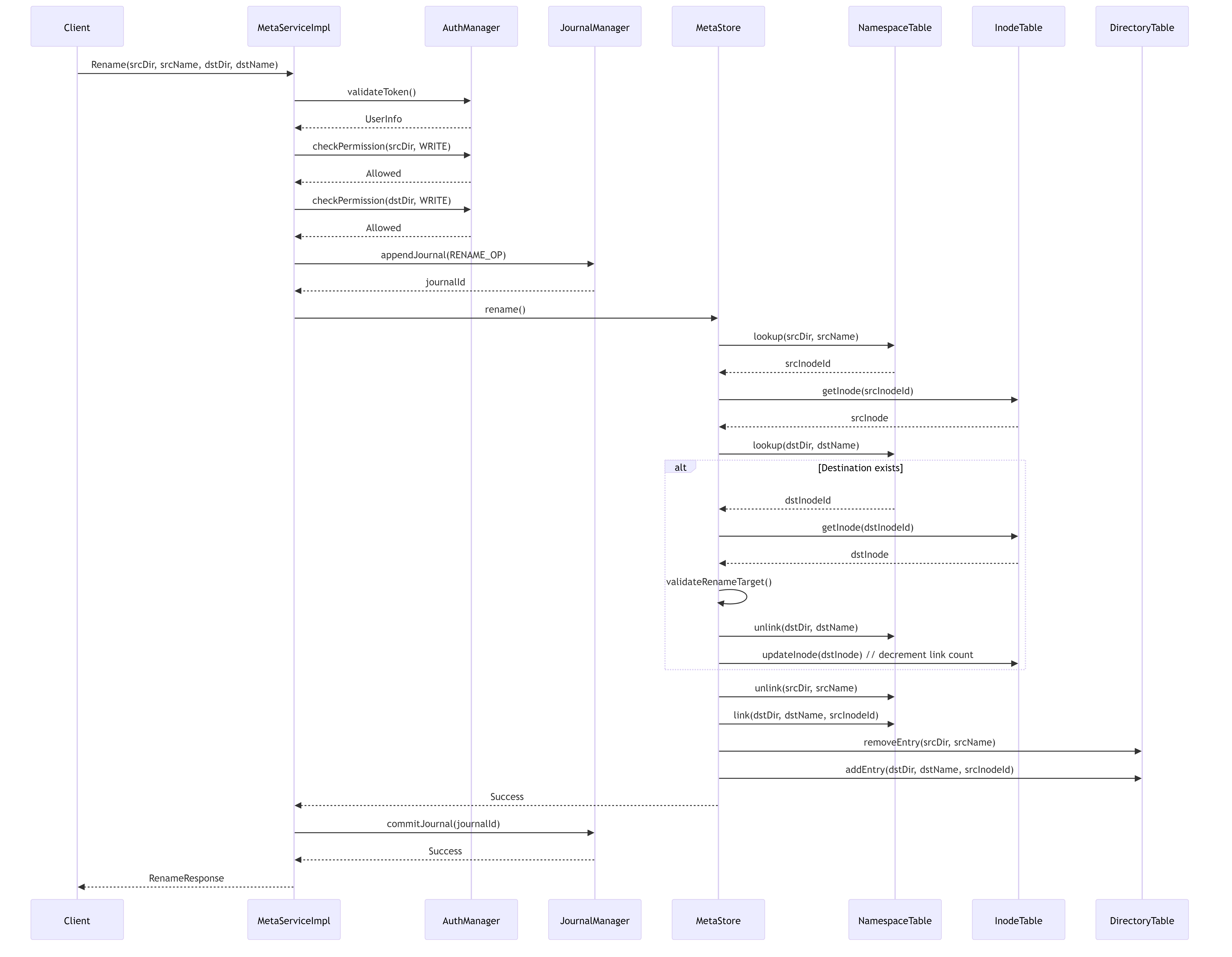
This diagram shows the workflow for renaming a file or directory, including namespace management.
5.5. Key Features
5.5.1. Hierarchical Namespace Management
The metadata service provides a complete hierarchical namespace with directories, files, and links. The NamespaceTable maps (parent directory ID, name) pairs to inode IDs, while the DirectoryTable maintains the list of entries in each directory.
5.5.2. Caching and Performance Optimization
The MetadataCache component caches frequently accessed inodes and directory listings to reduce database lookups and improve performance. It implements LRU (Least Recently Used) eviction policies to manage memory usage.
5.5.3. Journaling and Crash Recovery
The JournalManager implements write-ahead logging to ensure metadata operations can be recovered in case of crashes. All metadata-modifying operations are first recorded in the journal before being applied to the main database.
5.5.4. Access Control and Security
The AuthManager component validates user tokens and performs permission checks based on standard Unix-style permissions stored in the inode attributes. It supports user and group-based access control.
5.5.5. Quota Management
The QuotaManager tracks and enforces storage quotas per user or group. It maintains usage statistics and prevents operations that would exceed allocated quotas.
5.5.6. Distributed Coordination
For multi-node deployments, the metadata service includes mechanisms for coordination, leader election, and replication to ensure high availability and consistency across the cluster.
5.5.7. Extensible Attribute Support
The XattrTable provides storage and retrieval of extended attributes (xattrs) for files and directories, supporting custom metadata beyond standard file attributes.
5.6. Conclusion
The 3FS metadata service provides a robust and efficient system for managing filesystem metadata. Its modular design separates concerns between storage, caching, access control, and networking, allowing for flexible deployment and scaling options. The journaling system ensures data integrity even in the face of system failures, while the caching mechanisms optimize performance for common operations.
6. Management Daemon (MGMTD) Architecture (src/mgmtd)
This document outlines the architecture of the Management Daemon (MGMTD) in the 3FS system. MGMTD serves as the central coordination and management service that handles cluster configuration, node registration, heartbeats, and routing information.
6.1. Main Components Overview
The MGMTD service consists of several core components that work together to provide cluster management functionality.
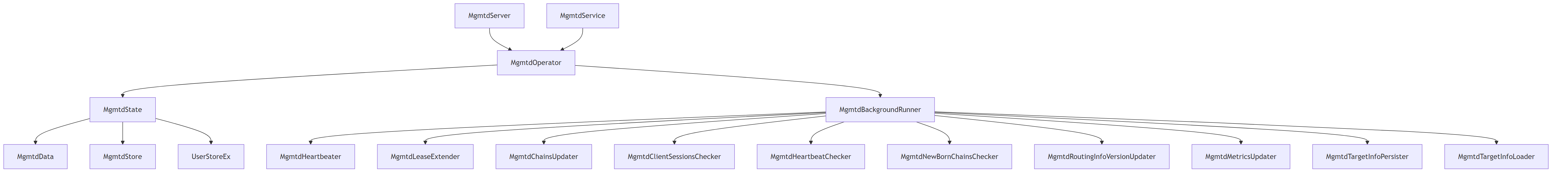
Key Components:
- MgmtdServer: Main entry point for the MGMTD service
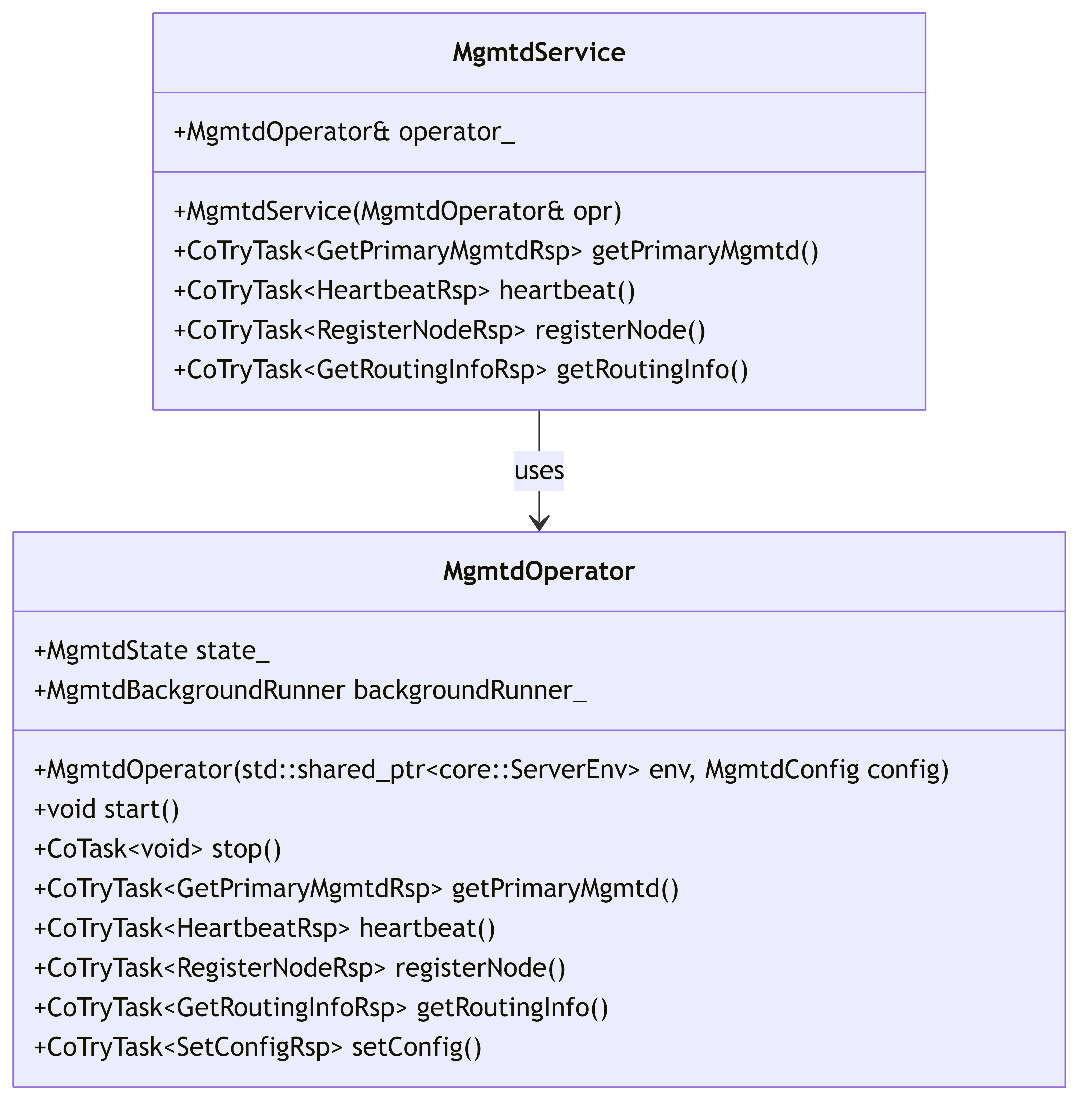
- MgmtdOperator: Handles operations exposed by the service interface
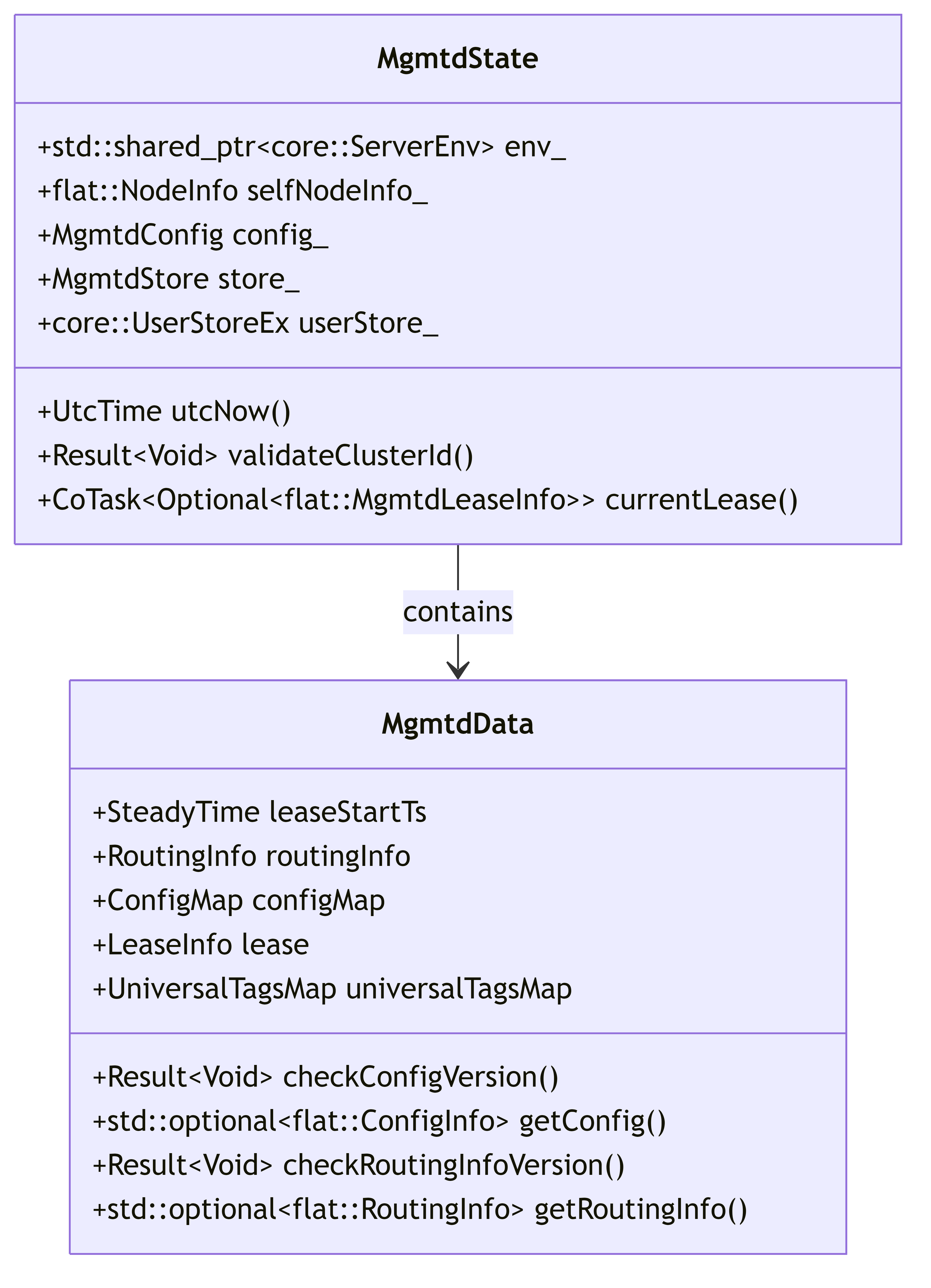
- MgmtdState: Maintains the current state of the cluster
- MgmtdData: Stores routing information, configurations, and other cluster data
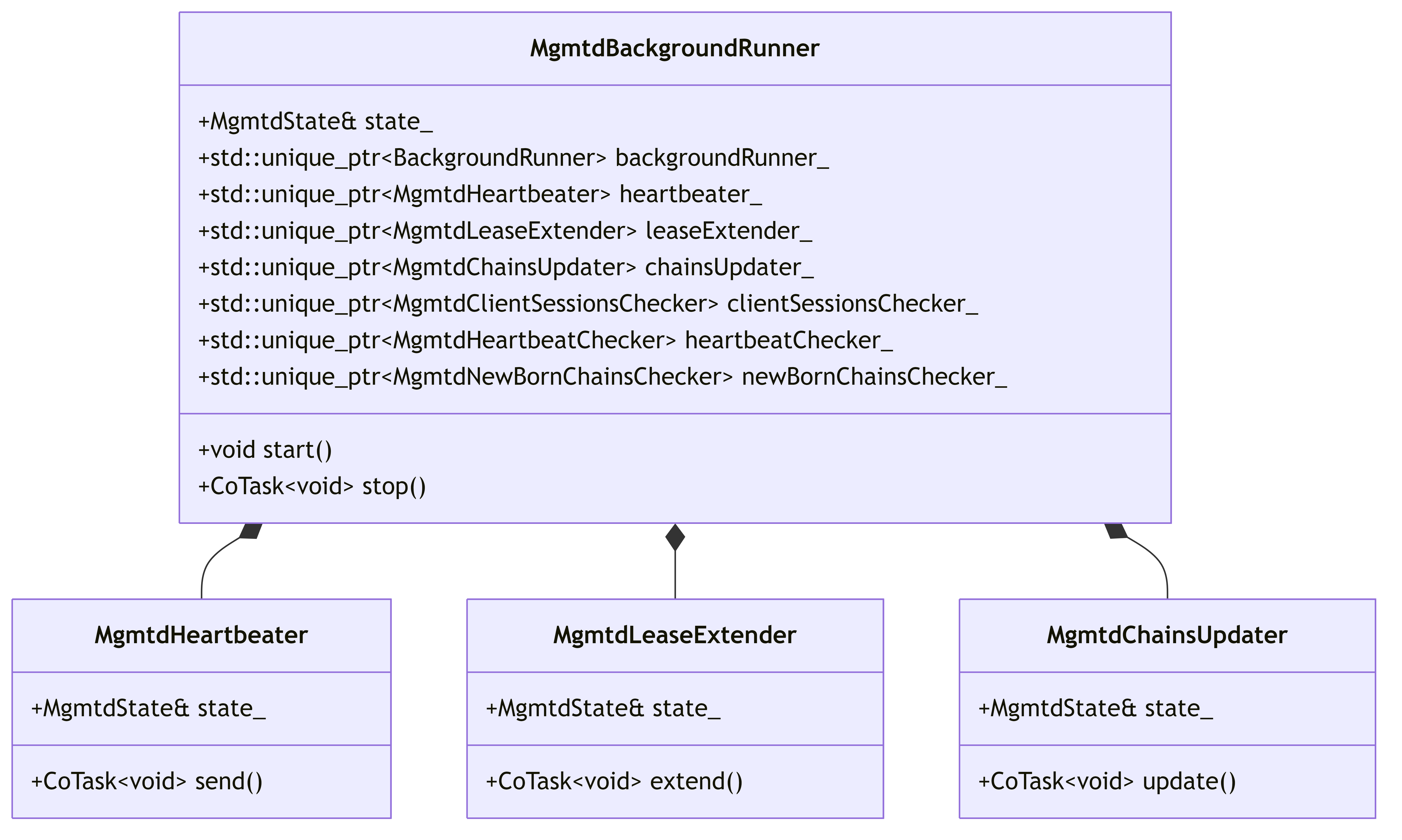
- MgmtdBackgroundRunner: Manages background tasks like heartbeats and lease extensions
- MgmtdStore: Handles persistence of MGMTD data
- MgmtdService: RPC service interface for client interaction
6.2. Component Structure and Responsibilities
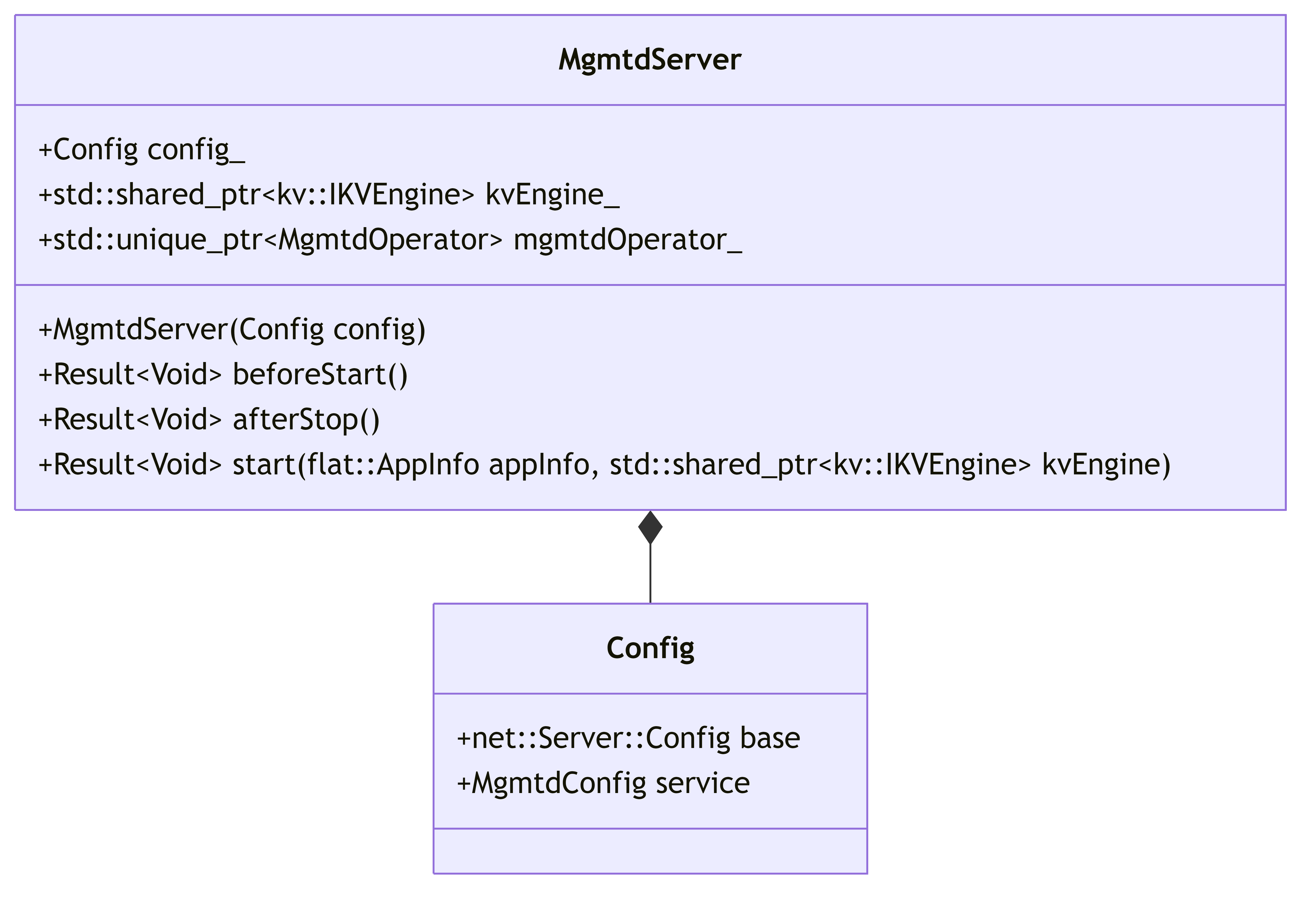
6.2.1. MgmtdServer
The entry point for the MGMTD service that initializes and coordinates all components.
6.2.2. MgmtdState and MgmtdData
These components maintain the state and data of the cluster.
6.2.3. MgmtdBackgroundRunner and Background Services
Manages various background processes that keep the cluster operating.
6.2.4. MgmtdOperator and Service Interface
Handles the RPC interface and service operations.
6.3. Key Workflows
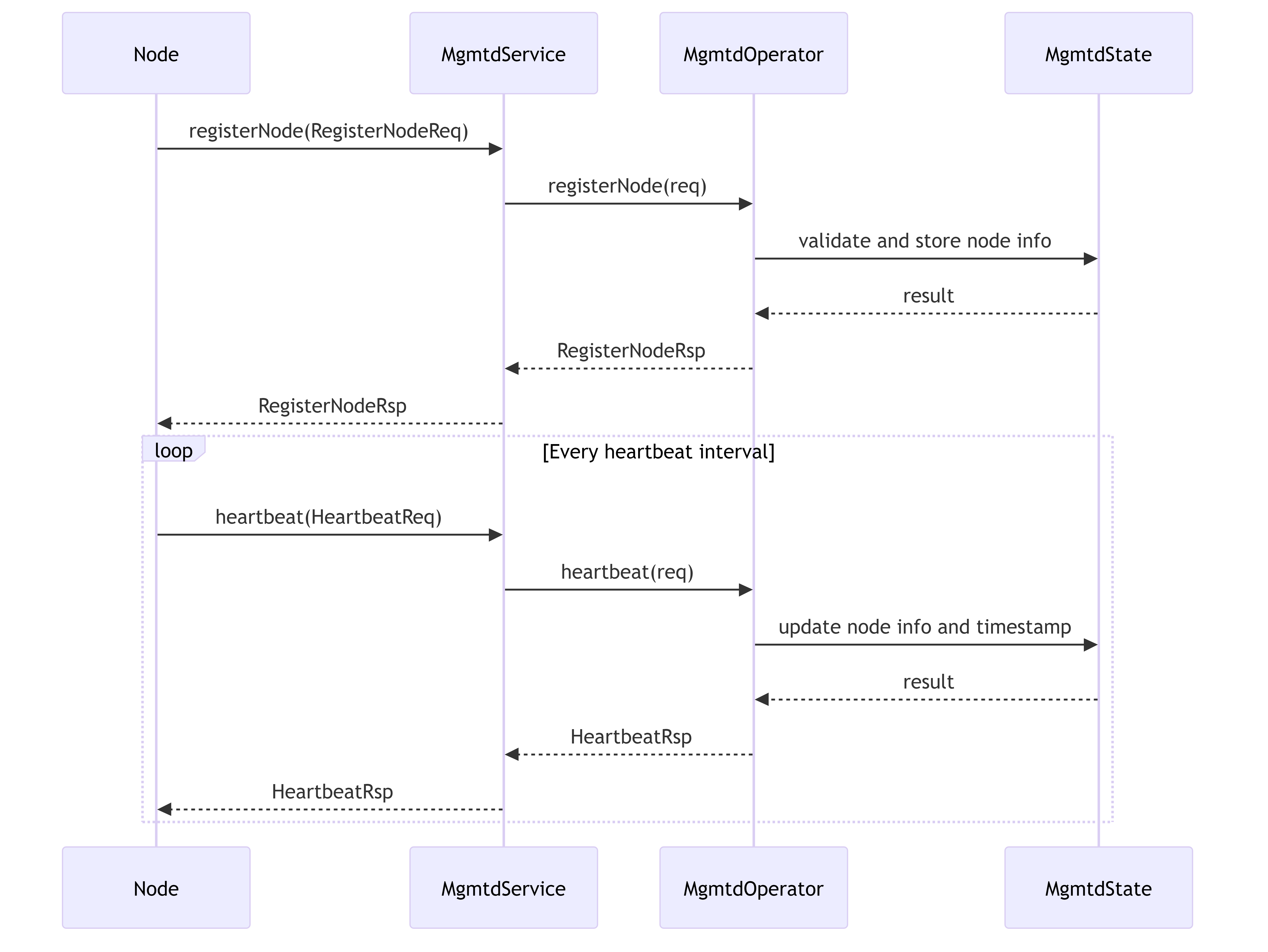
6.3.1. Node Registration and Heartbeat Flow
Shows how nodes register with MGMTD and maintain their presence through heartbeats.
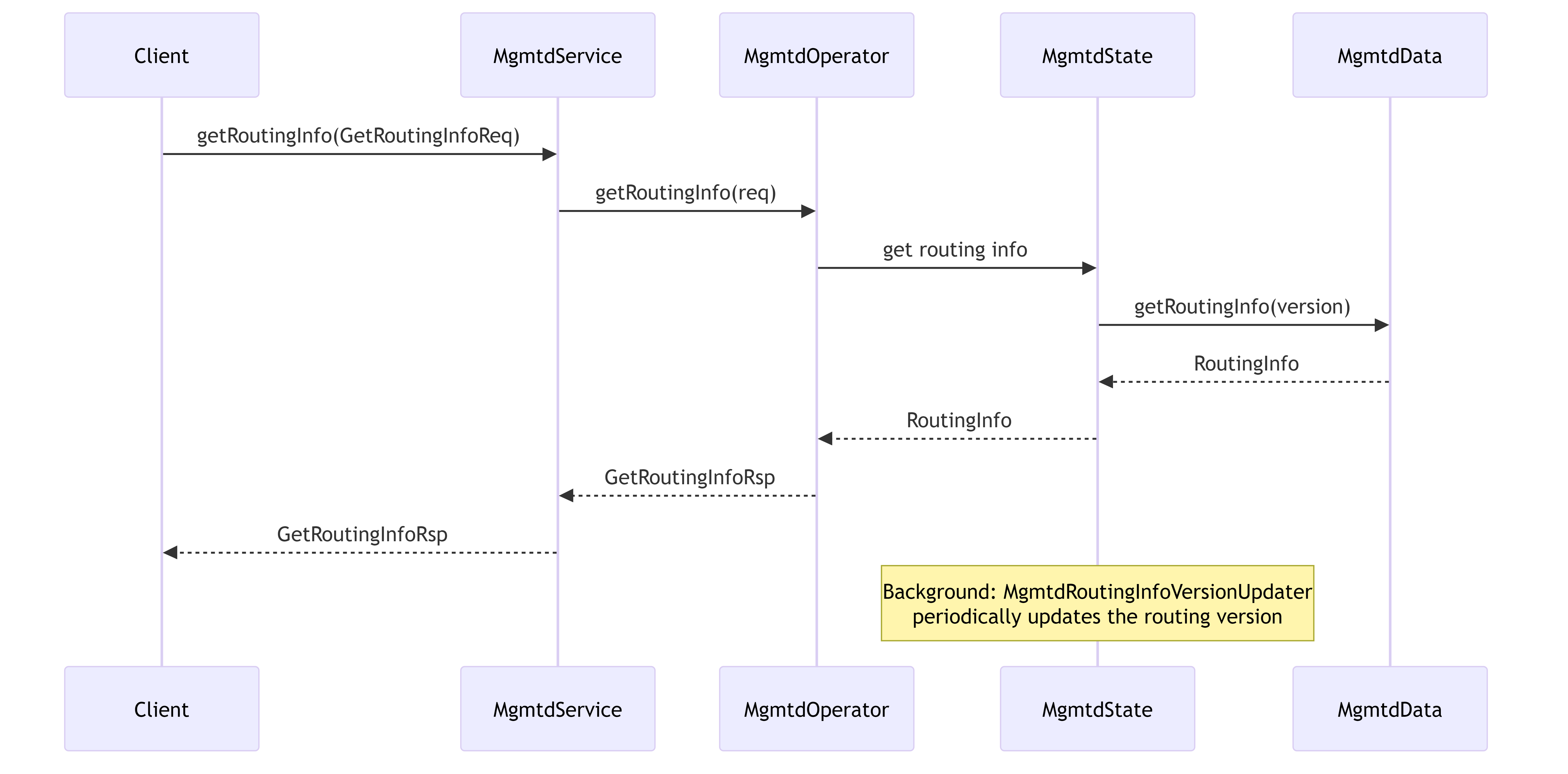
6.3.2. Routing Information Distribution
Illustrates how routing information is maintained and distributed to clients.
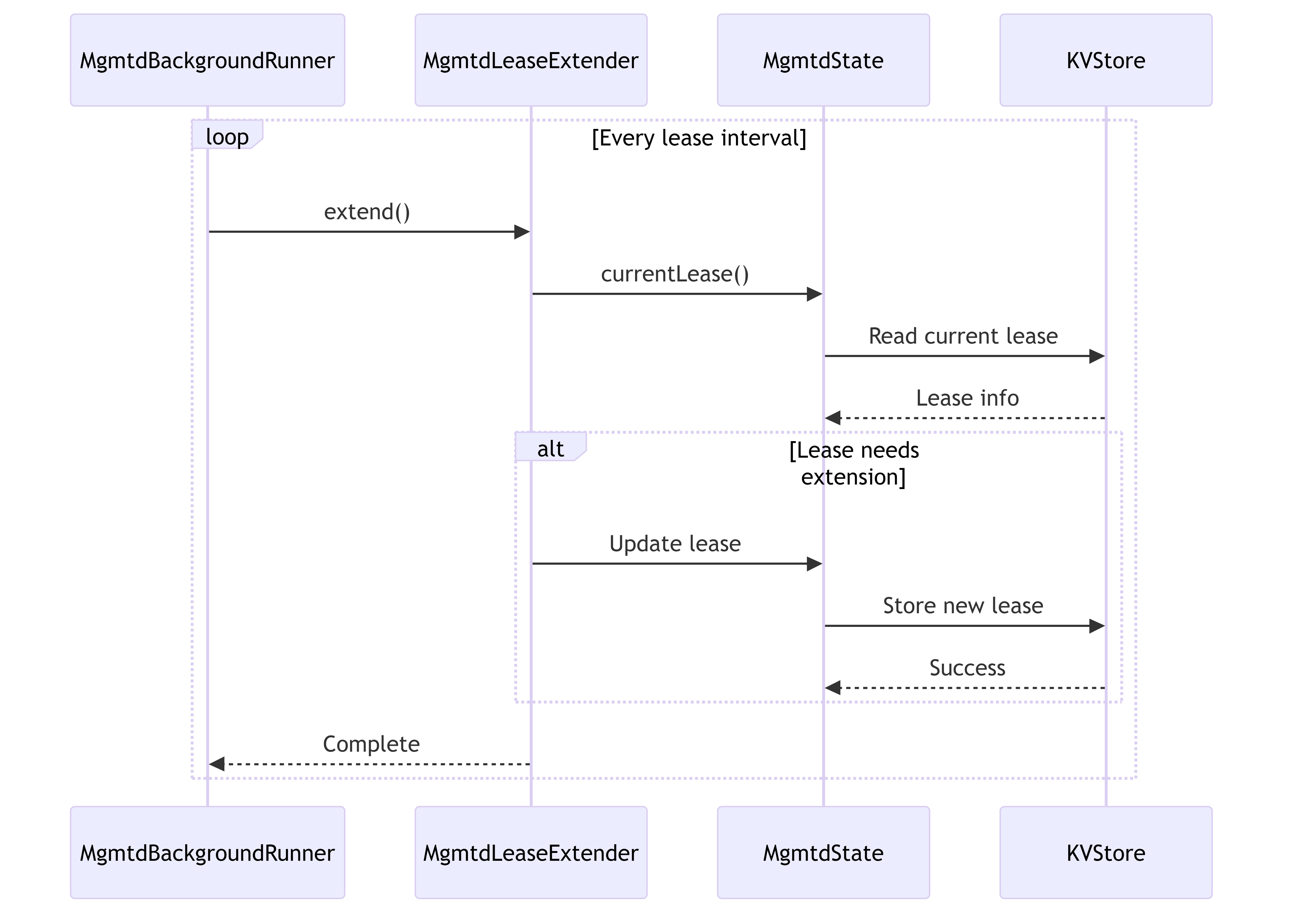
6.3.3. Lease Management
Shows how MGMTD manages cluster leases for primary MGMTD coordination.
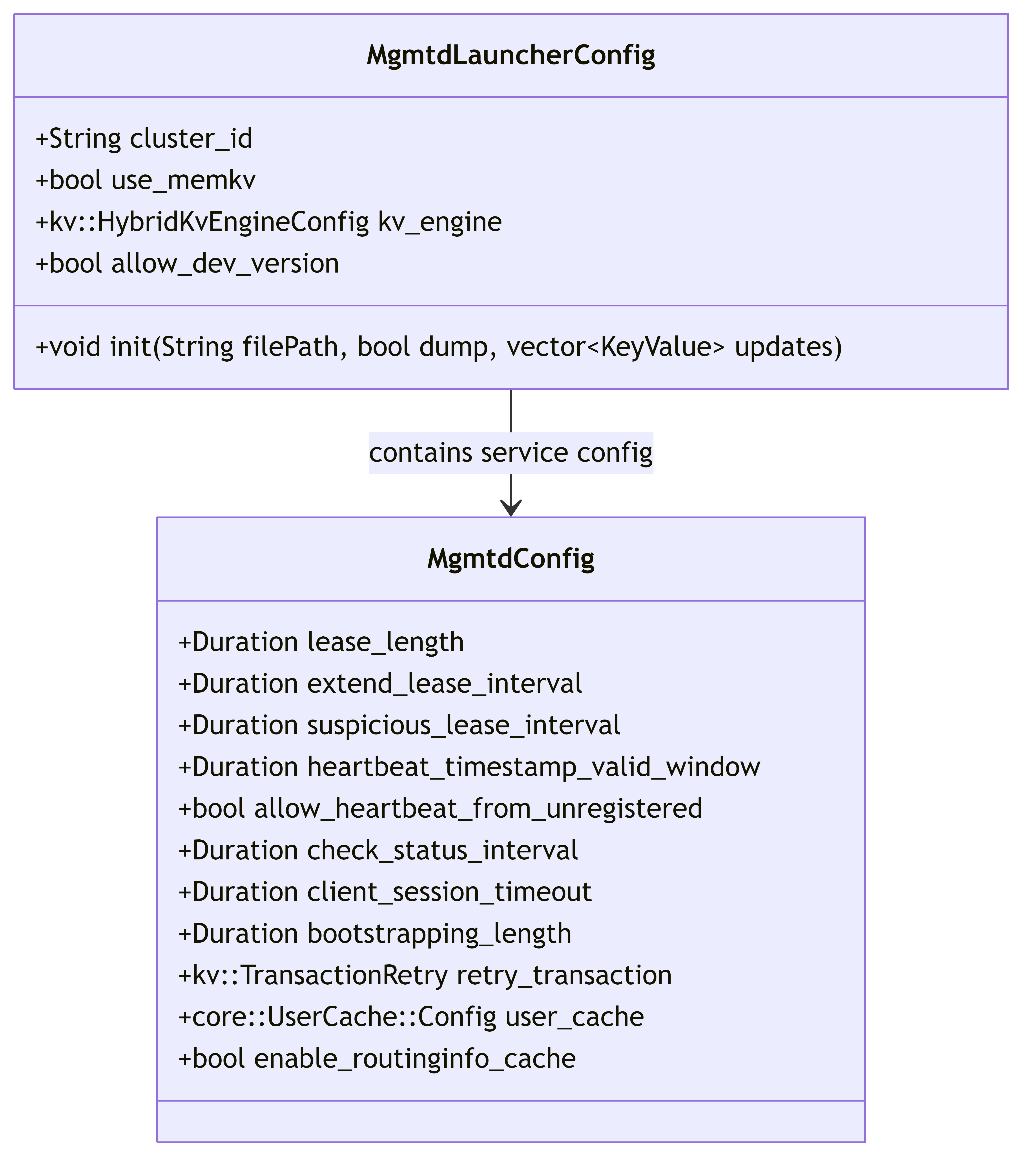
6.4. Configuration Management
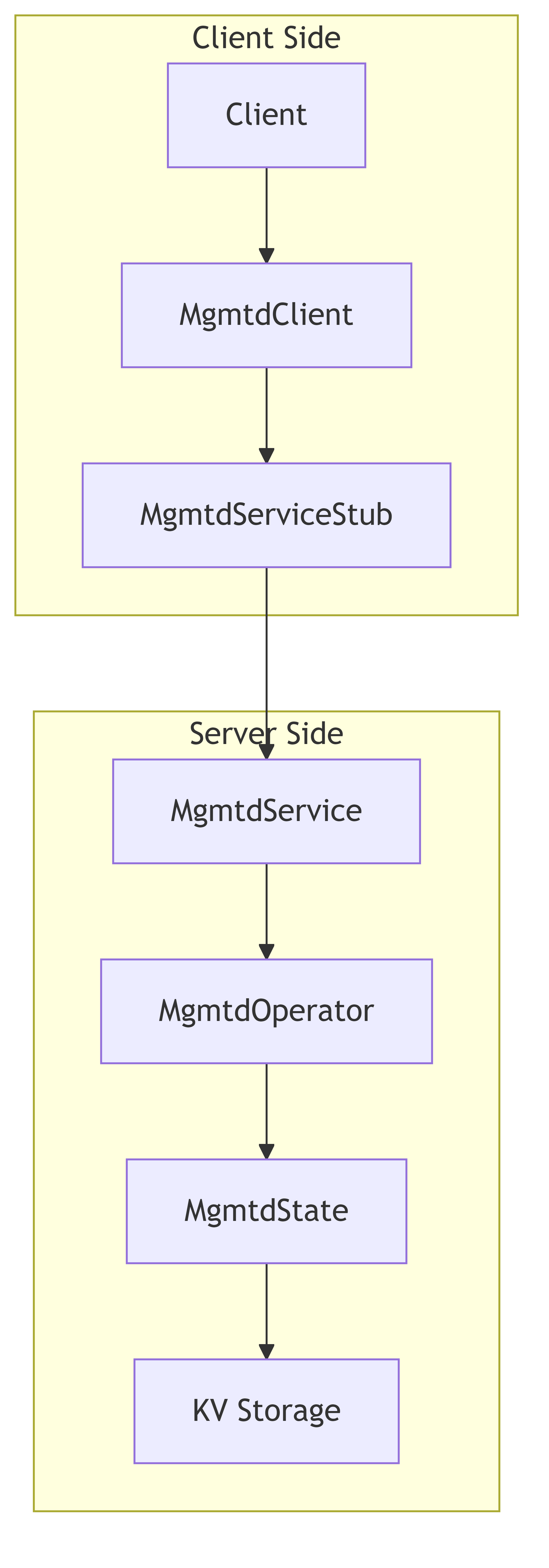
6.5. Client-Service Interaction
6.6. Functional Overview
6.6.1. Primary Responsibilities of MGMTD
- Cluster Membership Management
- Node registration and tracking
- Heartbeat monitoring
- Node status management (enable/disable)
- Configuration Management
- Storing and distributing node configurations
- Version control for configurations
- Config updates and validation
- Routing Information Management
- Maintaining cluster topology
- Distributing routing tables
- Version control for routing information
- Lease Management
- Primary MGMTD election
- Lease acquisition and extension
- Failover coordination
- Chain Management
- Chain table configuration
- Chain creation, updates and monitoring
- Target ordering and rotation
- Client Session Management
- Session tracking
- Session timeout monitoring
- Session extension
- Background Monitoring and Maintenance
- Heartbeat checking
- Target information persistence
- Chain updates
- Metrics collection and reporting
The MGMTD service plays a central role in the 3FS system by maintaining the cluster state, coordinating nodes, and ensuring proper distribution of configuration and routing information to all components.
7. 3FS Storage Architecture (src/storage)
This document outlines the architecture of the storage subsystem in the 3FS distributed filesystem. The storage layer is responsible for persisting and retrieving chunk data efficiently while maintaining data integrity and high performance.
7.1. Overview
The 3FS storage subsystem provides a reliable, high-performance distributed storage solution. It manages data chunks across multiple storage targets, handles concurrent read/write operations, and provides mechanisms for data replication and recovery.
7.2. Key Components
The storage subsystem consists of several key components organized in a layered architecture:
- Storage Service Layer - External interface that handles client requests
- Storage Operator - Coordinates operations across storage targets
- Target Management - Handles storage target lifecycle and distribution
- Chunk Store - Manages physical storage of data chunks
- Replication Protocol - Chain Replication for Atomic Queriable Replication (CRAQ)
7.3. Architecture Diagrams
7.3.1. Component Architecture
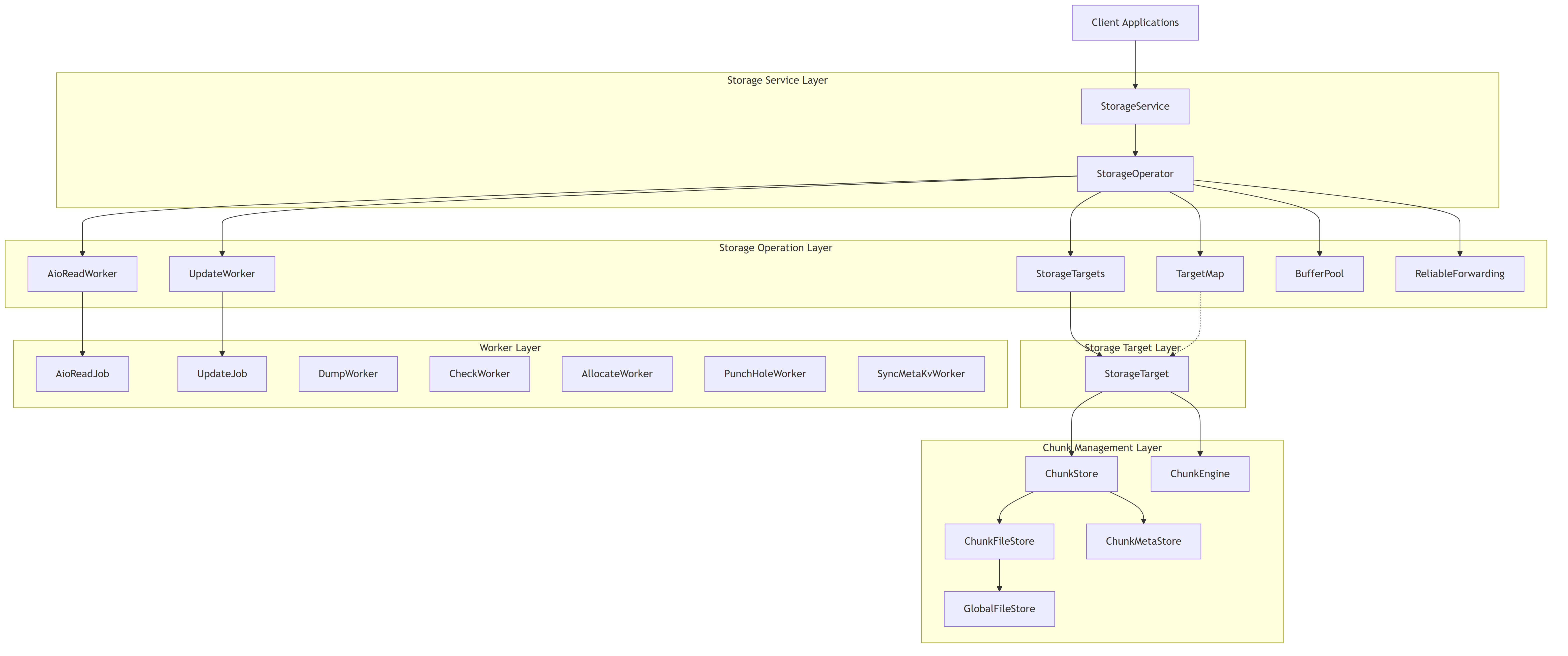
The diagram above shows the main components of the storage architecture and their relationships. The storage system is organized in layers, with each layer responsible for different aspects of the storage functionality.
7.3.2. Request Processing Workflow
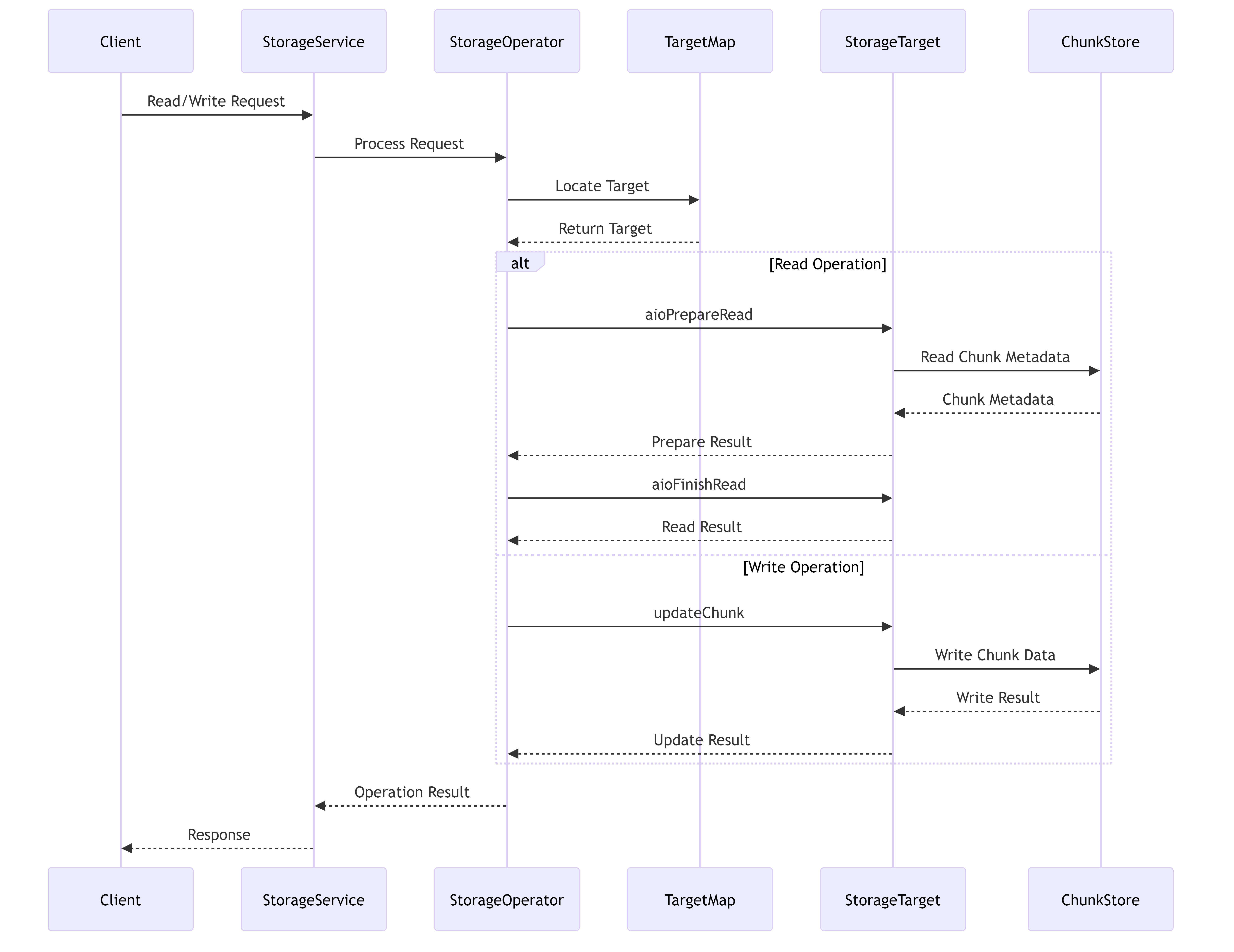
This diagram illustrates how read and write requests flow through the storage system, showing the interaction between different components during request processing.
7.3.3. Storage Target Management
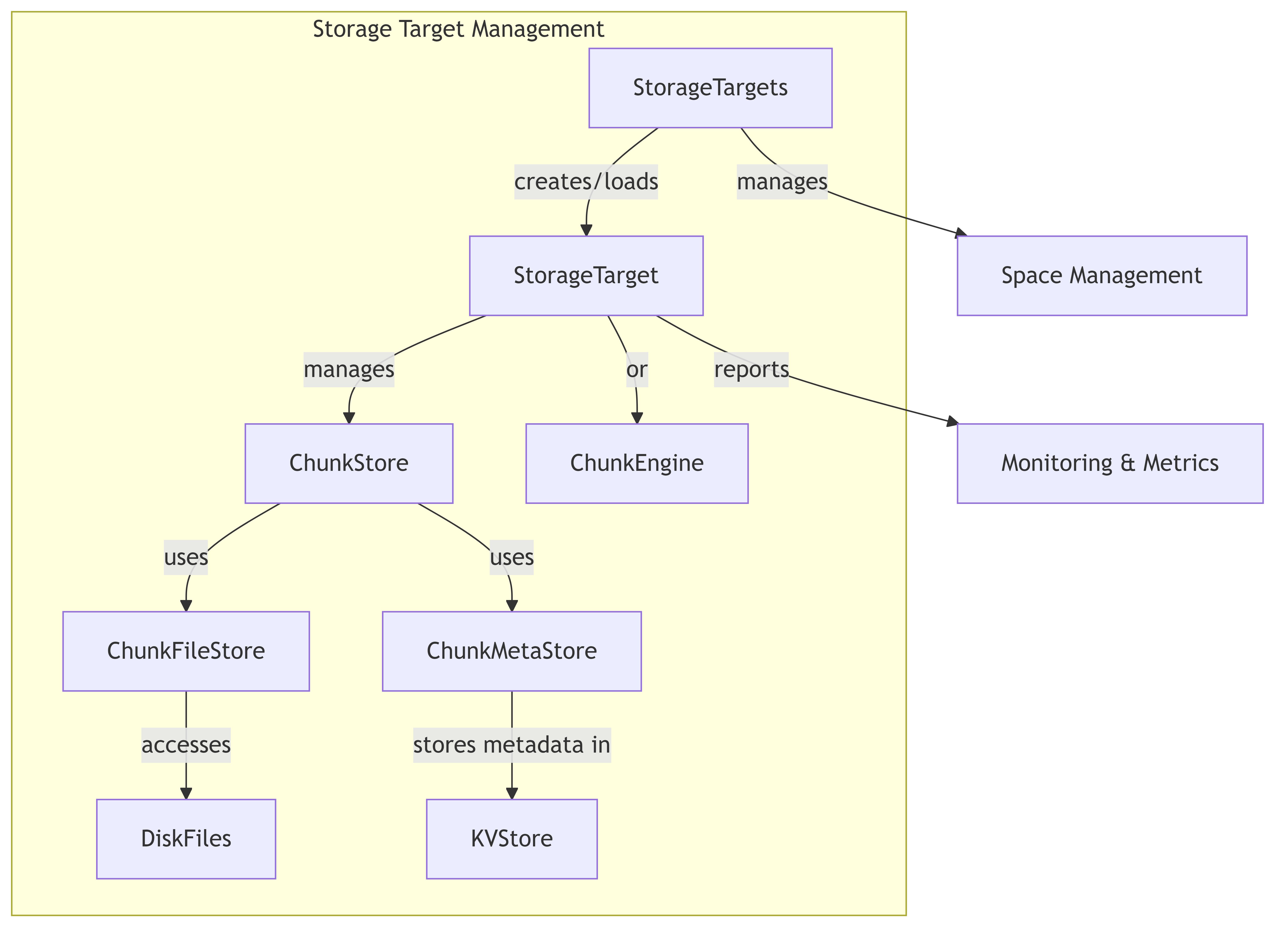
This diagram shows how storage targets are managed in the system, illustrating the relationship between targets and the underlying storage mechanisms.
7.4. Main Components Description
7.4.1. Storage Service Layer
- StorageService: Exposes storage functionality as RPC services, handling client requests for operations like read, write, update, and chunk management.
7.4.2. Storage Operation Layer
- StorageOperator: Coordinates operations across storage targets, implementing the core functionality for read/write operations, space management, and target coordination.
- BufferPool: Manages memory buffers for I/O operations to optimize memory usage and reduce allocations.
- ReliableForwarding: Ensures reliable data forwarding across storage nodes in a replication chain.
7.4.3. Storage Target Layer
- StorageTargets: Manages a collection of storage targets, handling target creation, loading, and space information.
- TargetMap: Maintains a mapping of chain IDs to storage targets for efficient target lookup.
- StorageTarget: Represents an individual storage target, managing chunk operations and metadata for a specific target.
7.4.4. Chunk Management Layer
- ChunkStore: Manages chunk data and metadata, providing an interface for operations like read, write, and query.
- ChunkEngine: Alternative implementation of chunk management using a Rust-based engine.
- ChunkFileStore: Handles the physical storage of chunks in files.
- ChunkMetaStore: Manages chunk metadata storage in a key-value store.
- GlobalFileStore: Provides a global view of file descriptors across the storage system.
7.4.5. Worker Layer
- AioReadWorker: Handles asynchronous I/O read operations.
- UpdateWorker: Processes chunk update operations (write, remove, truncate).
- DumpWorker: Performs background dump operations for storage data.
- CheckWorker: Executes verification and health check tasks.
- AllocateWorker: Manages chunk allocation operations.
- PunchHoleWorker: Reclaims storage space by punching holes in sparse files.
- SyncMetaKvWorker: Synchronizes metadata in the key-value store.
7.5. Key Workflows
7.5.1. Read Operation
- Client sends a read request to StorageService
- StorageService delegates to StorageOperator
- StorageOperator identifies the target via TargetMap
- StorageOperator prepares the read using AioReadWorker
- StorageTarget accesses the chunk data from ChunkStore or ChunkEngine
- Data is returned through the service layers back to the client
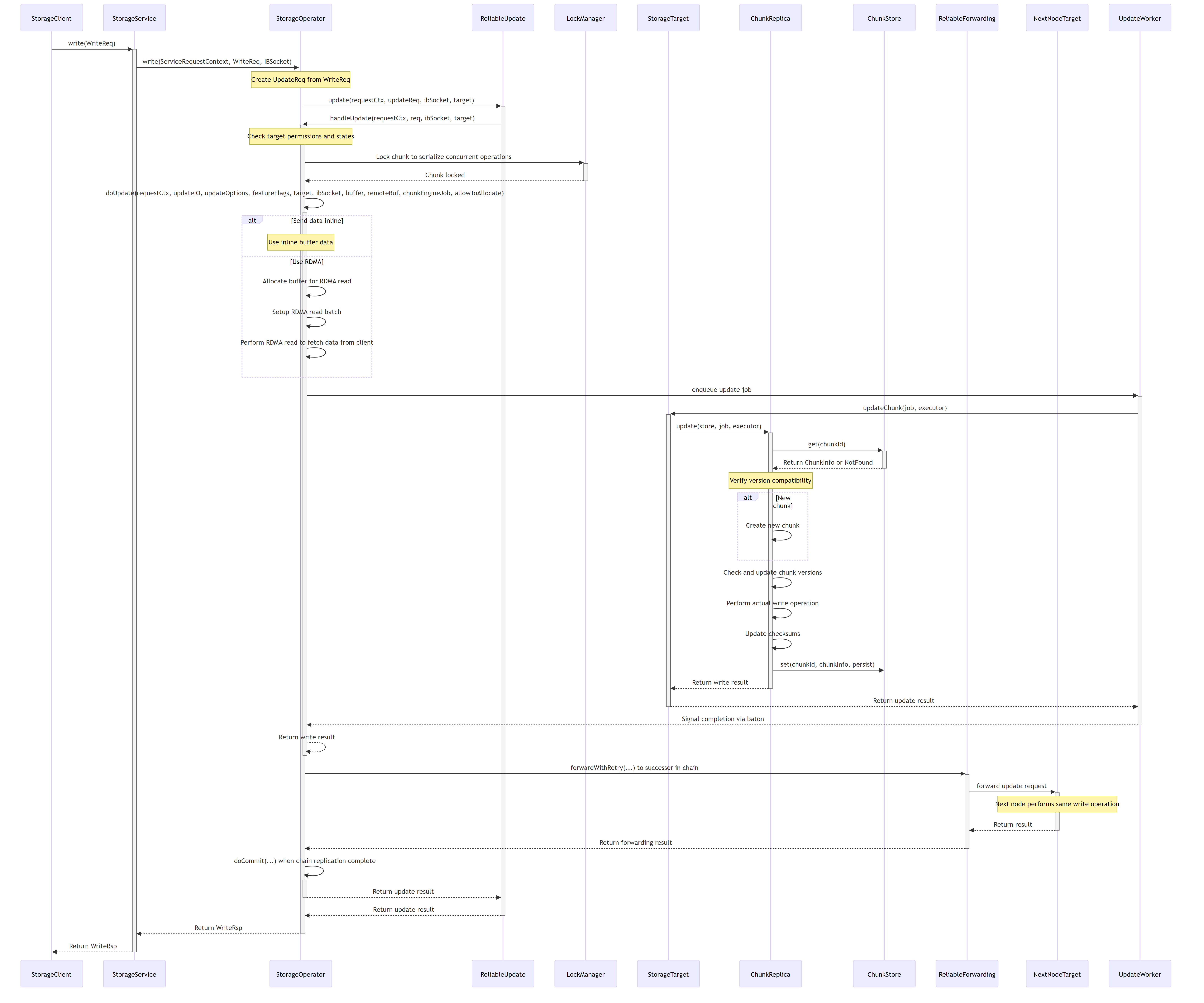
7.5.2. Write Operation
- Client sends a write request to StorageService
- StorageService delegates to StorageOperator
- StorageOperator identifies the target via TargetMap
- StorageOperator initiates the write operation
- StorageTarget updates the chunk using ChunkStore or ChunkEngine
- Optional forwarding to next replica via ReliableForwarding
- Result is returned to the client
7.5.3. Target Management
- StorageTargets creates or loads targets based on configuration
- Each StorageTarget initializes ChunkStore or ChunkEngine
- StorageTargets registers targets in the TargetMap
- Space information is collected and maintained for management decisions
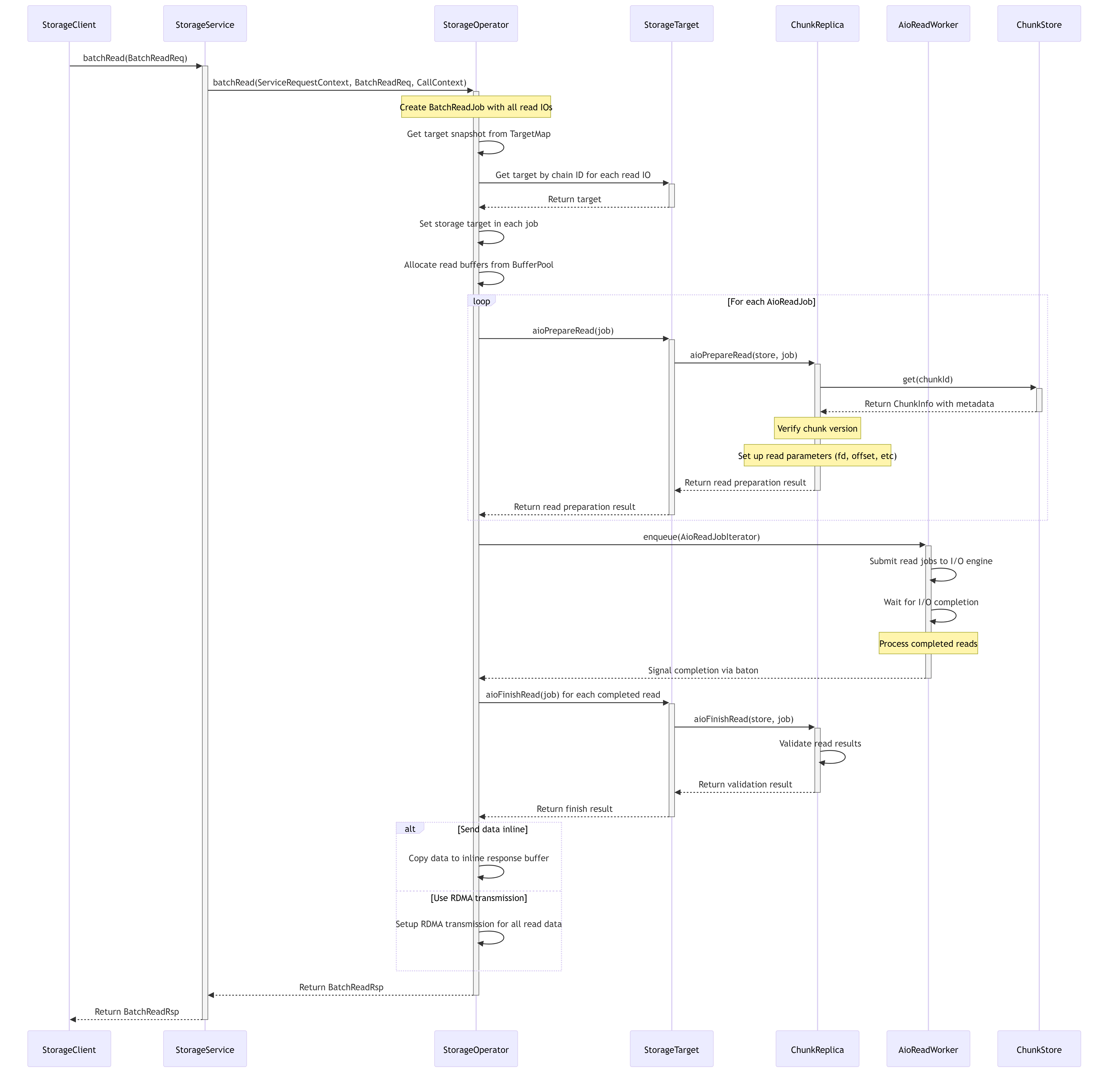
7.6. Read Processing Flow
The following sequence diagram illustrates how read requests are processed in the 3FS storage system:
7.7. Write Processing Flow
The following sequence diagram illustrates how write requests are processed in the 3FS storage system, including the chain replication protocol:
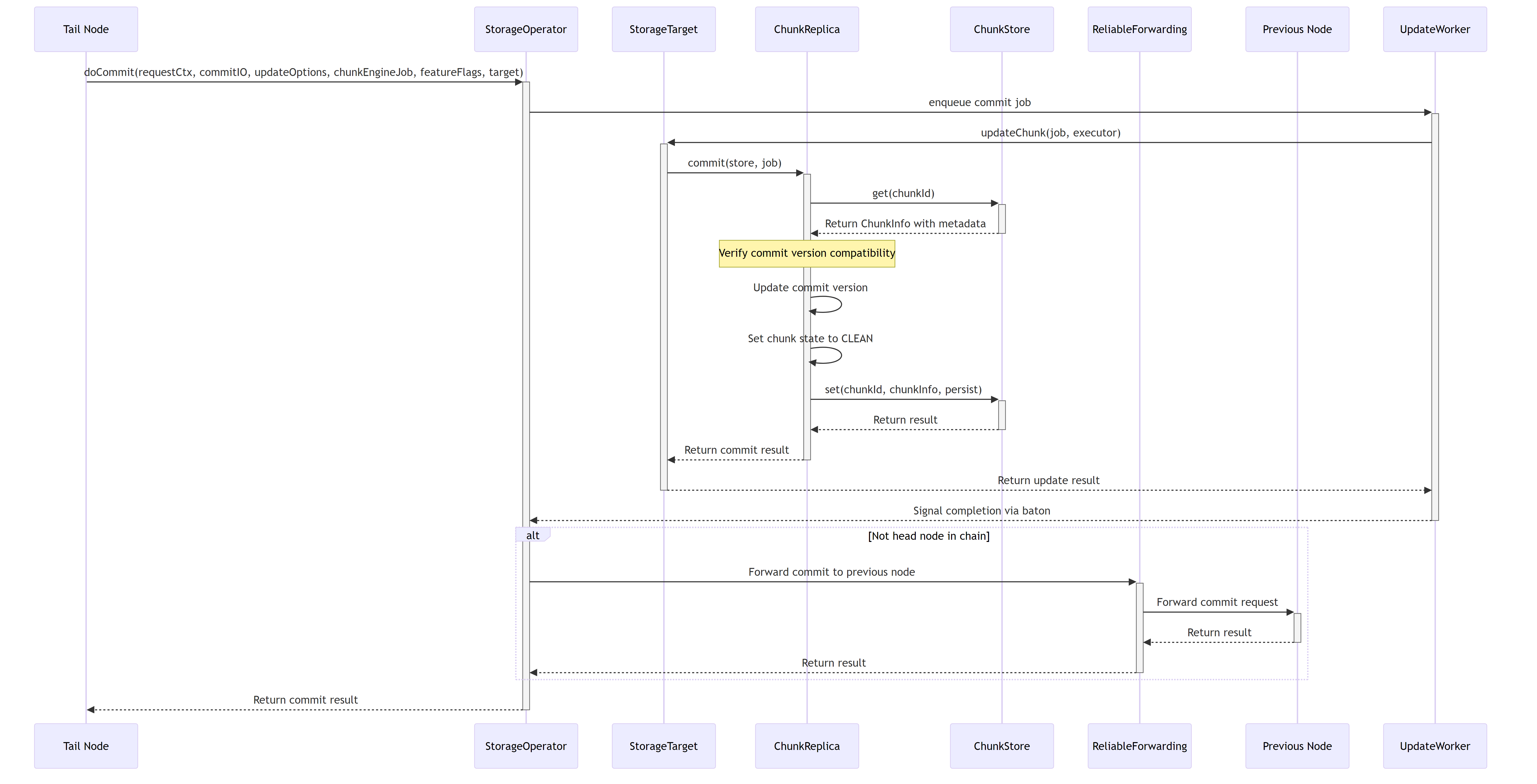
7.8. Commit Process Flow
The commit operation is a critical part of the CRAQ protocol, which ensures data is durably stored and consistent across replicas. The following sequence diagram illustrates how the commit process works in 3FS:
7.9. Chunk Allocation Management
The chunk allocation system is responsible for efficiently managing the lifecycle of chunks in the storage system. Below is a detailed architecture diagram showing the components involved in chunk allocation:
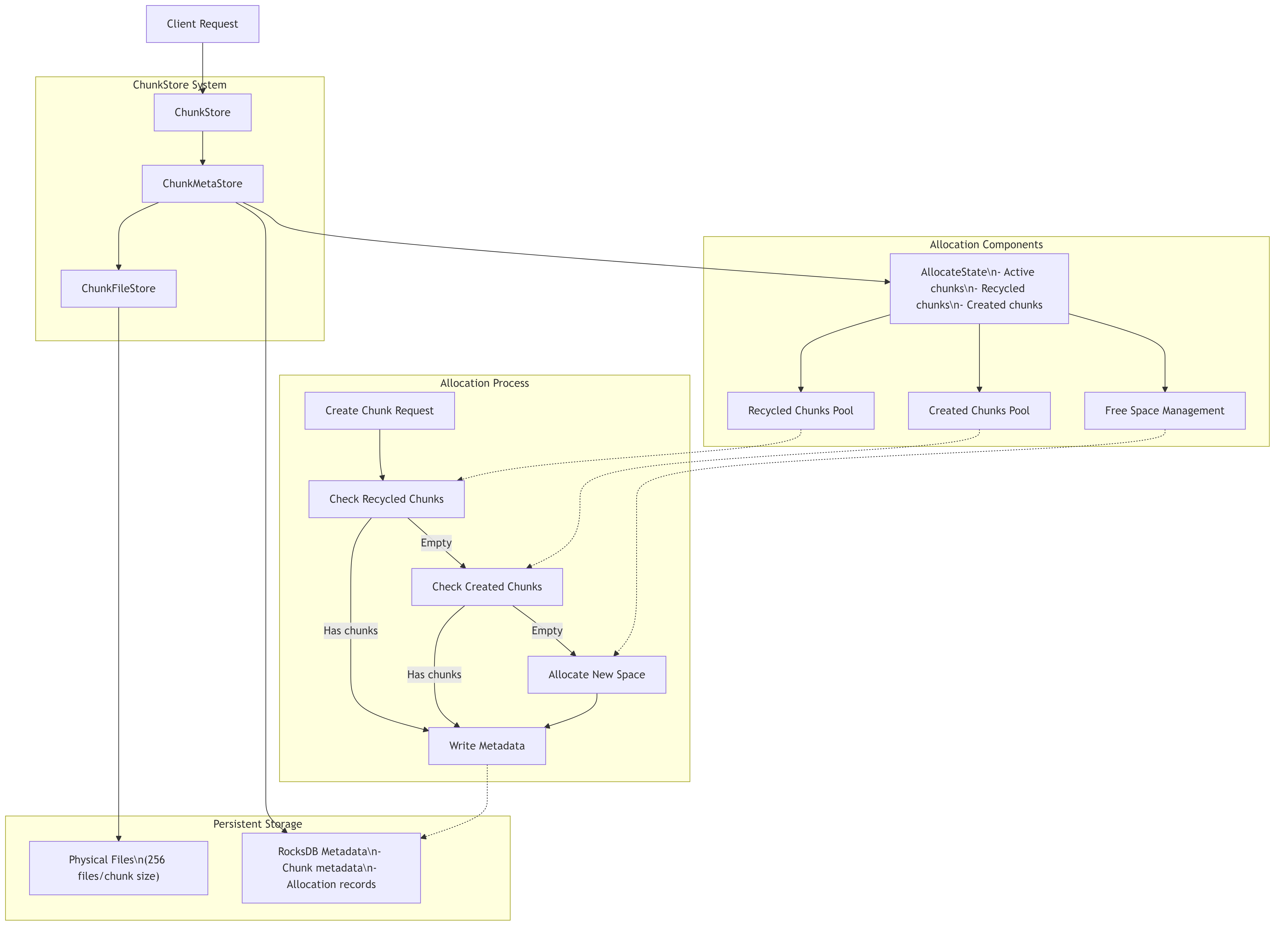
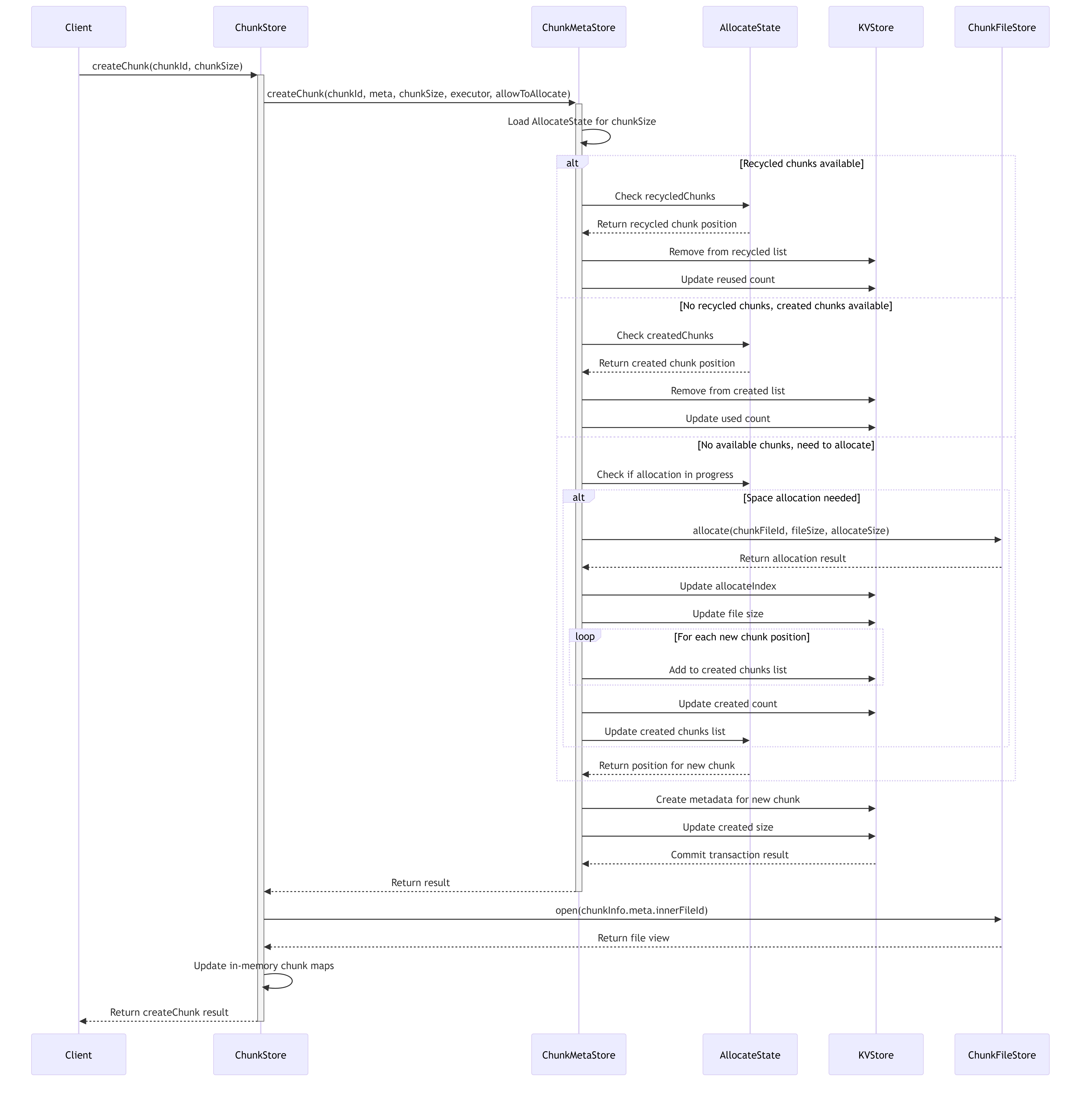
7.9.1. Detailed Chunk Allocation Process
The chunk allocation system follows a sophisticated process to efficiently allocate and recycle storage space:
7.10. Metadata Management System
The metadata management system is responsible for maintaining all chunk-related metadata in the storage system, providing a reliable and efficient way to track chunk states, versions, and physical locations.
7.10.1. Metadata Key Structure and Organization
The system organizes metadata keys in RocksDB using a structured prefix system to optimize retrieval and management:

7.11. Chunk Lifecycle Management
The following diagram illustrates the complete lifecycle of a chunk in the storage system:
7.12. Storage System Components
7.12.1. StorageOperator
The StorageOperator is the central coordination component that handles all storage operations. It manages:
- Read/write request handling
- Buffer allocation for data transfer
- Target selection and coordination
- RDMA data transfer
- Chain replication coordination
7.12.2. AioReadWorker
The AioReadWorker provides asynchronous I/O capabilities for read operations:
- Manages I/O thread pools
- Handles asynchronous reading from storage devices
- Supports both traditional AIO and io_uring interfaces
- Processes batches of read requests efficiently
7.12.3. ChunkReplica
ChunkReplica handles the actual storage operations on chunks:
- Read preparation and validation
- Write operations with version control
- Commit operations
- Checksum validation and update
7.12.4. Target Management
Storage targets are managed through:
- Dynamic addition and removal of targets
- Health monitoring and state management
- Replica distribution and balancing
- Chain formation and maintenance
7.12.5. ReliableForwarding
The ReliableForwarding component ensures that updates are properly propagated through the replication chain:
- Request forwarding to successor nodes
- Retry and failover mechanisms
- Consistency validation
- Chain version management
8. References
[1] VS Code Copilot Agent: https://github.blog/news-insights/product-news/github-copilot-the-agent-awakens/
[2] DeepSeek 3FS: https://github.com/deepseek-ai/3FS/tree/main/src/storage
Create an Issue or comment below